Followup to the Onewheel XS
-
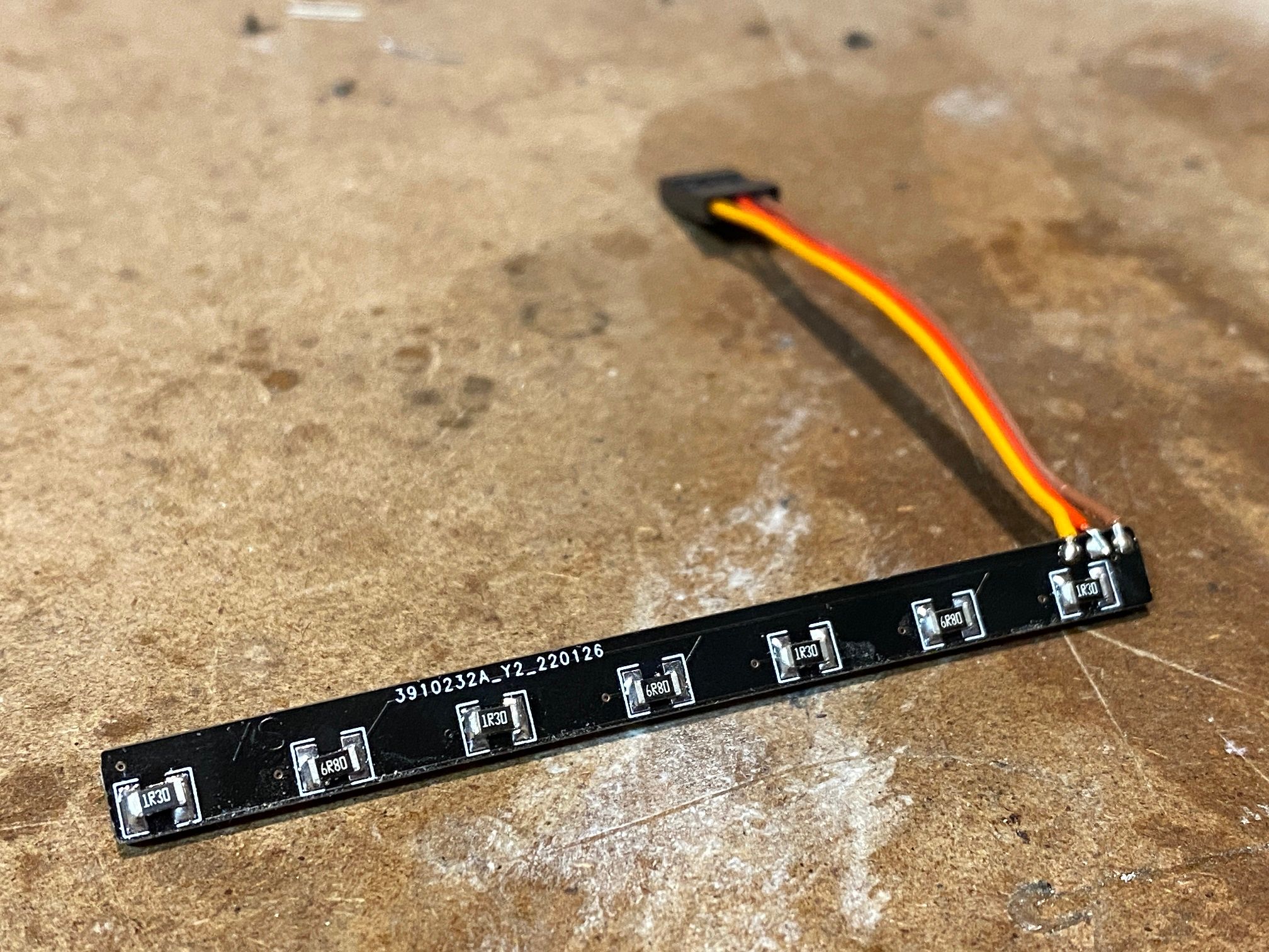
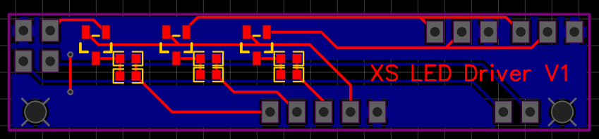
PCBs came for the headlights so will solder those up tomorrow (hopefully) :)
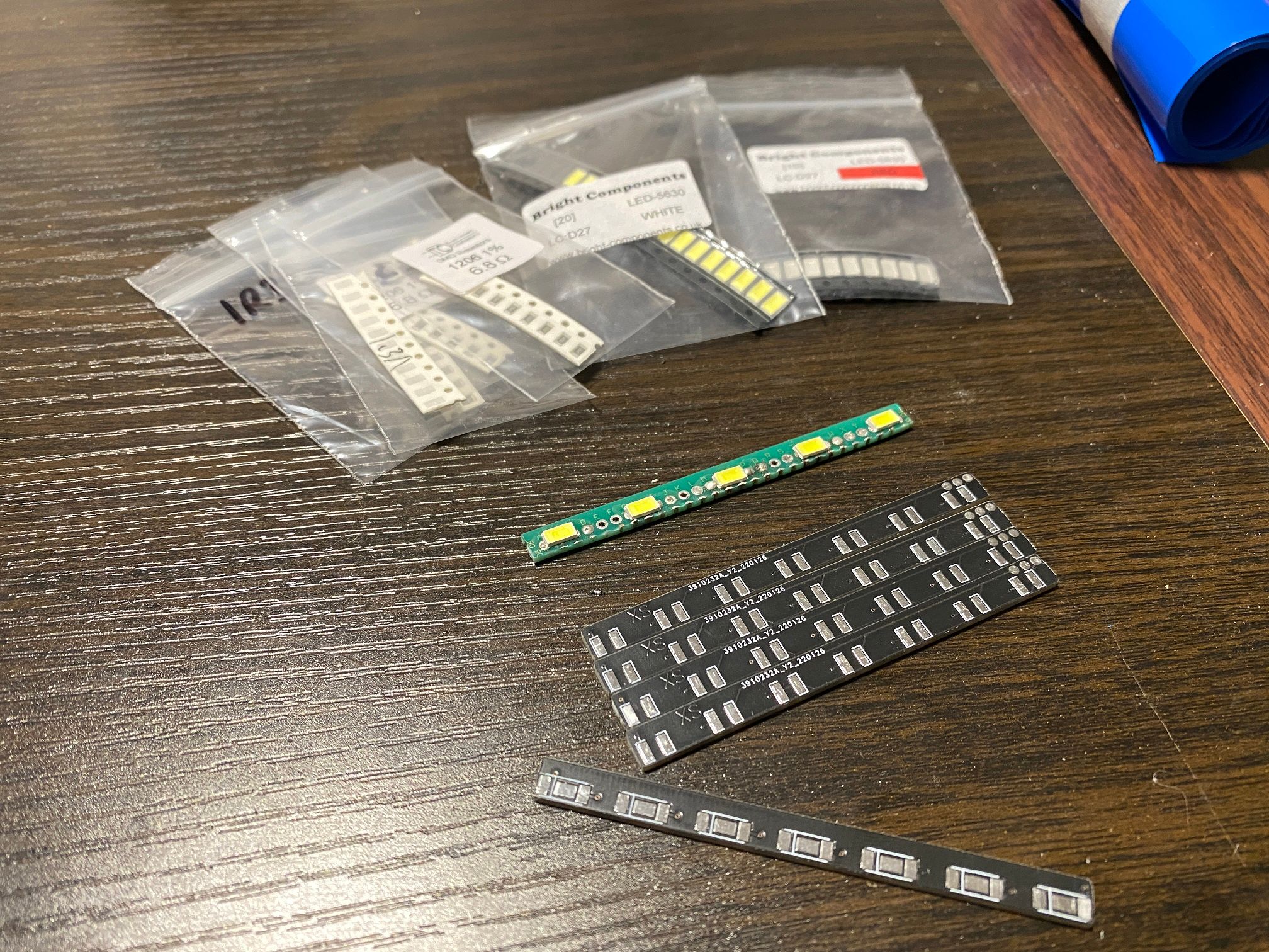
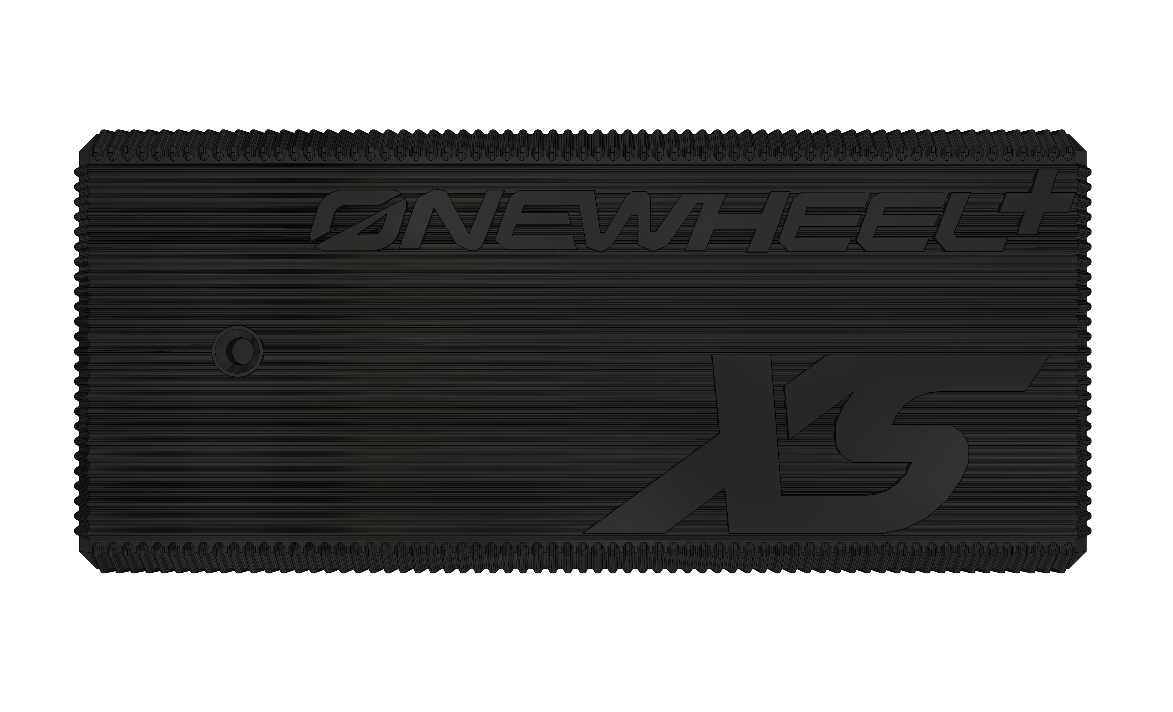
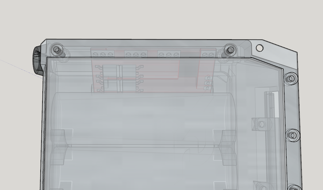
Min quantity was 5 so I have 3 spares for now.Also had the desire to make the charger so spent a few hours making a replica of that in Sketchup~
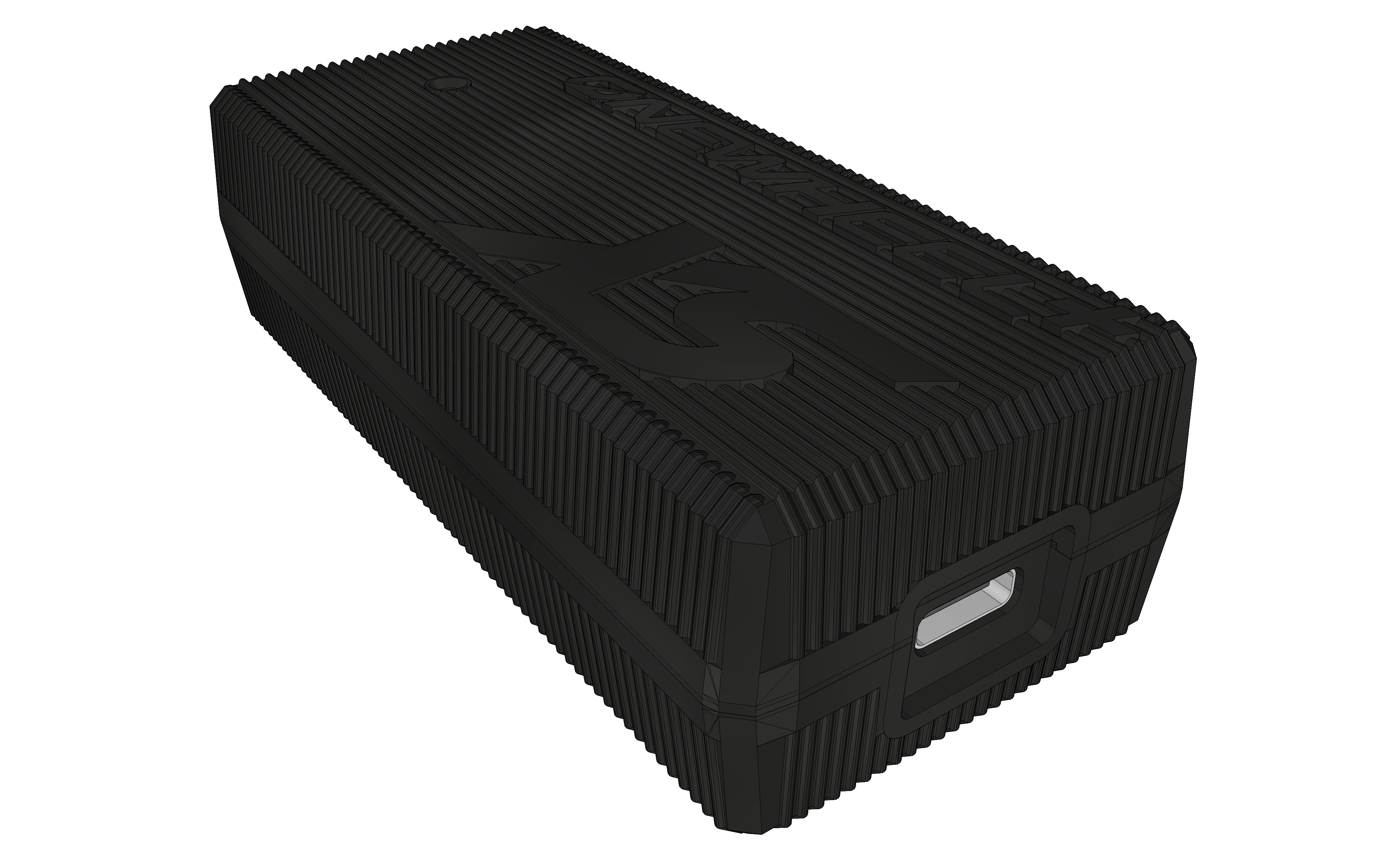
Will use a USB C interface in place of the normal C8 (figure 8) mains connector. Printed the top half and it came out okay.
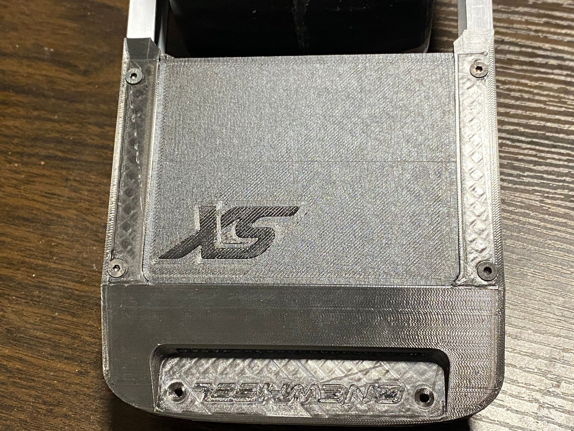
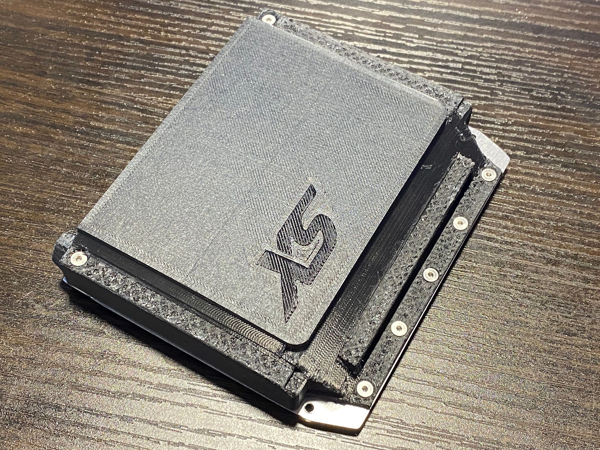
Also you can see I re-did the battery housing and rear bumpers in 0.1mm layer heights which makes a huge difference to the surface finish and detail retention. Also printing the bumpers upside-down helps a lot with making the "Onewheel" wording show up albeit hard to see through camera.
.
EDIT : Nevermind I had nothing else to do and flowing solder paste is quiet (minus my cursing as I burn myself). First time ever using solder paste and using the hot air part of my solder station properly. I don;t think I did too badly :)
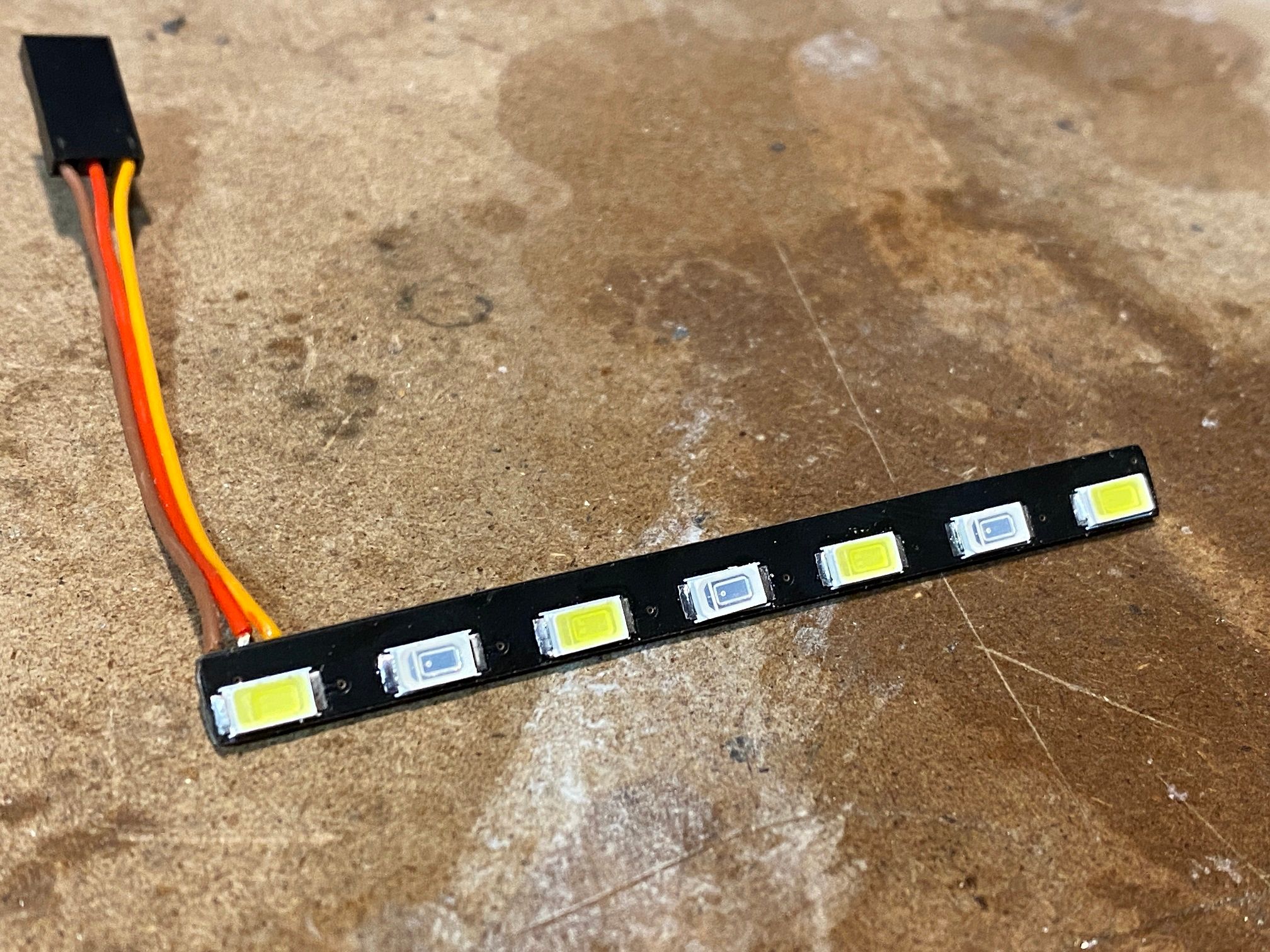
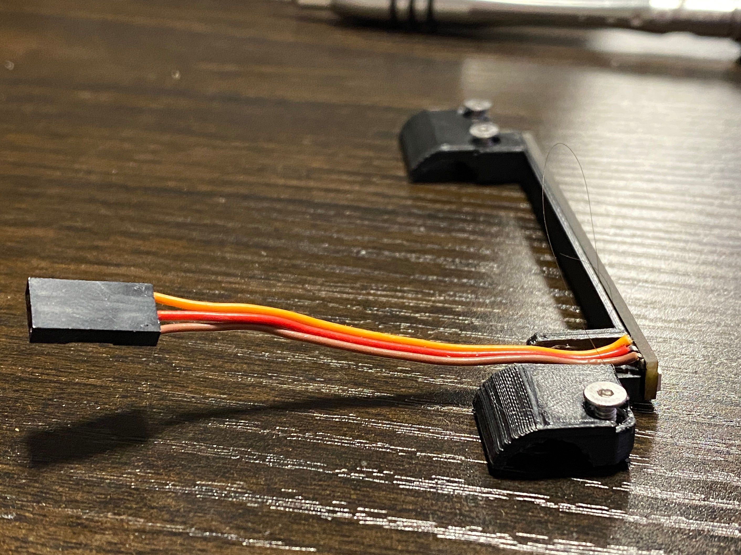
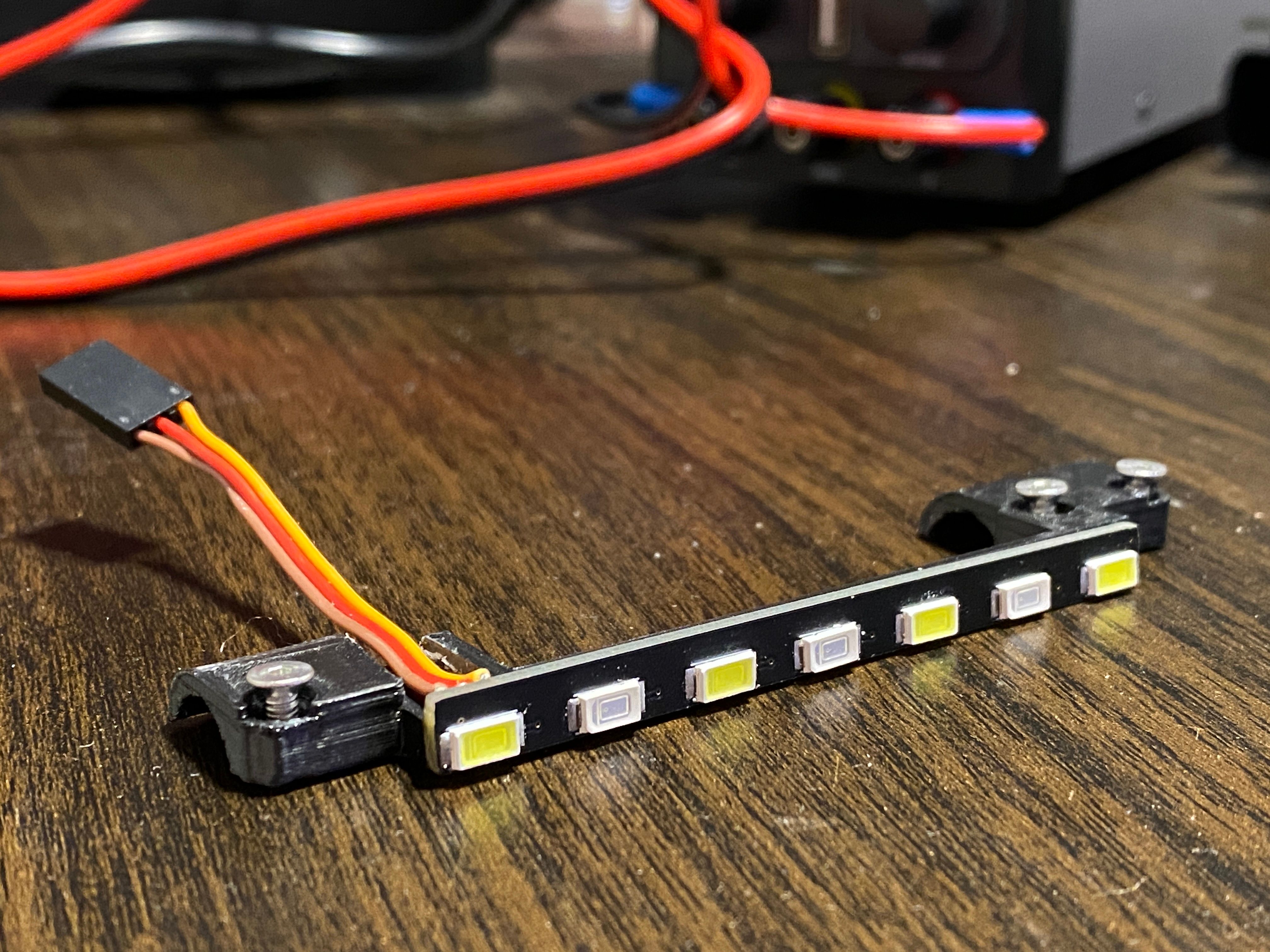
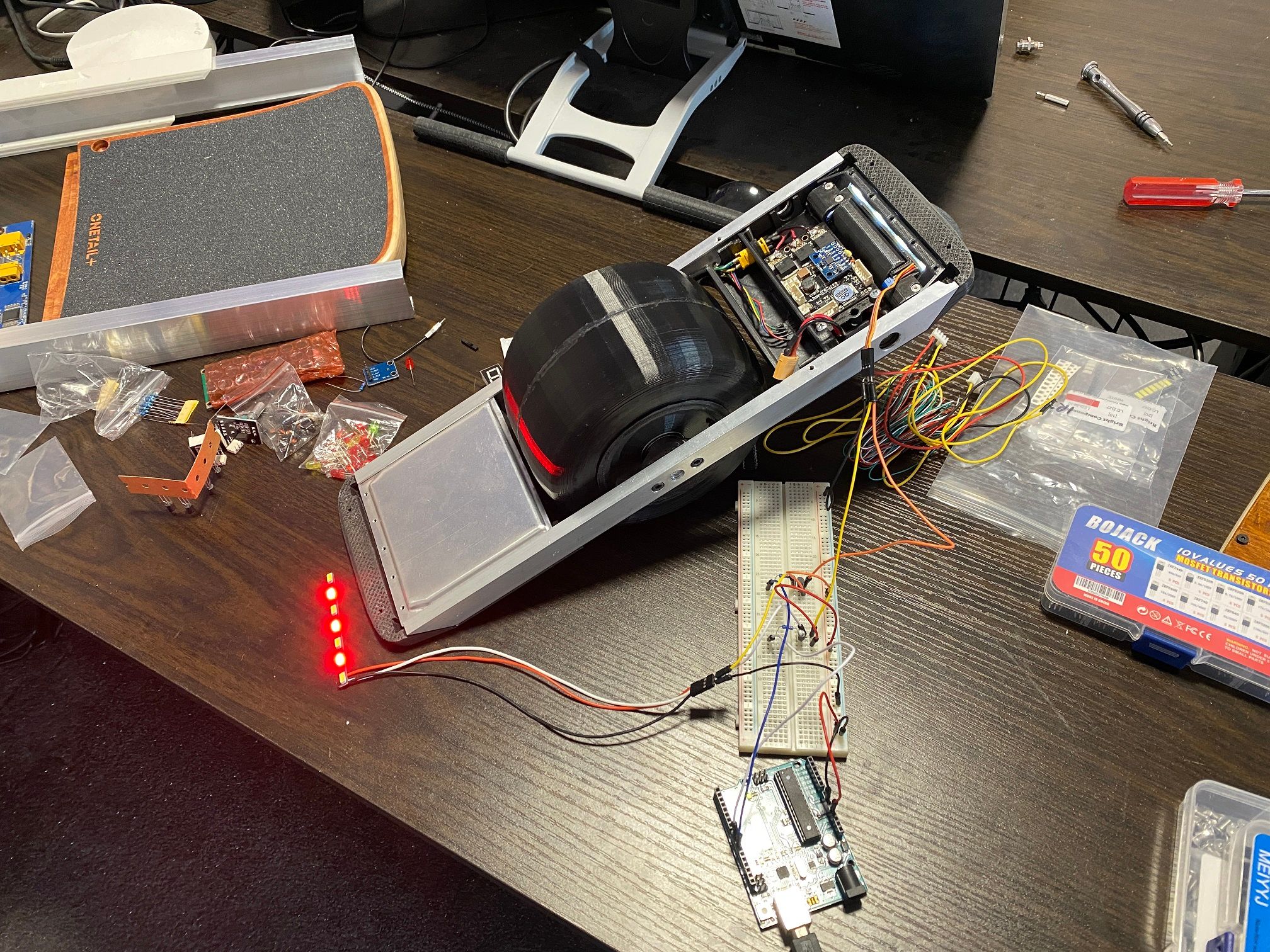
Here's a vid of me testing it. Didn't have a 3.3v supply handy so I just borrowed an old Arduino Uno I have laying around to pinch it's 3.3v rail. I realy should buy a decent lab bench power supply but all the ones that have voltage and current ranges I want are hella pricey.
Connector is temporary, just needed something easy to poke a jumper into for testing :)
Originally I was going to drive these off 5v but the drop required to get the LED's running at a proper voltage meant the resistors would have to be much bigger. At the time I was using more LED's so didn't have space. I could go back to 5 white 4 red but I think this is fine for the scale version.
-
@lia Literally drooling over this project and the most fascinating one i ve seen to date. You must make a limited run of these cause i'm pre-ordering NOW with the money FM did not take from me yet .
Aka "Vommbat"
-
@Lia my brain be like:
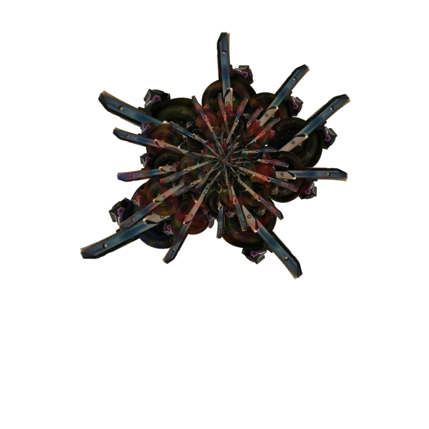
... and yes of course its a png with transparent canvas! what am i? an animal?XR's got what plants crave!
-
@notsure Very trippy, nice work rotoscoping that :)

PNG is best format~ -
-
@maciak So happy to hear that <3
It is tempting, make a few commissioned ones for some riders. If I do have a change of heart and consider it I'll let you know ;)
-
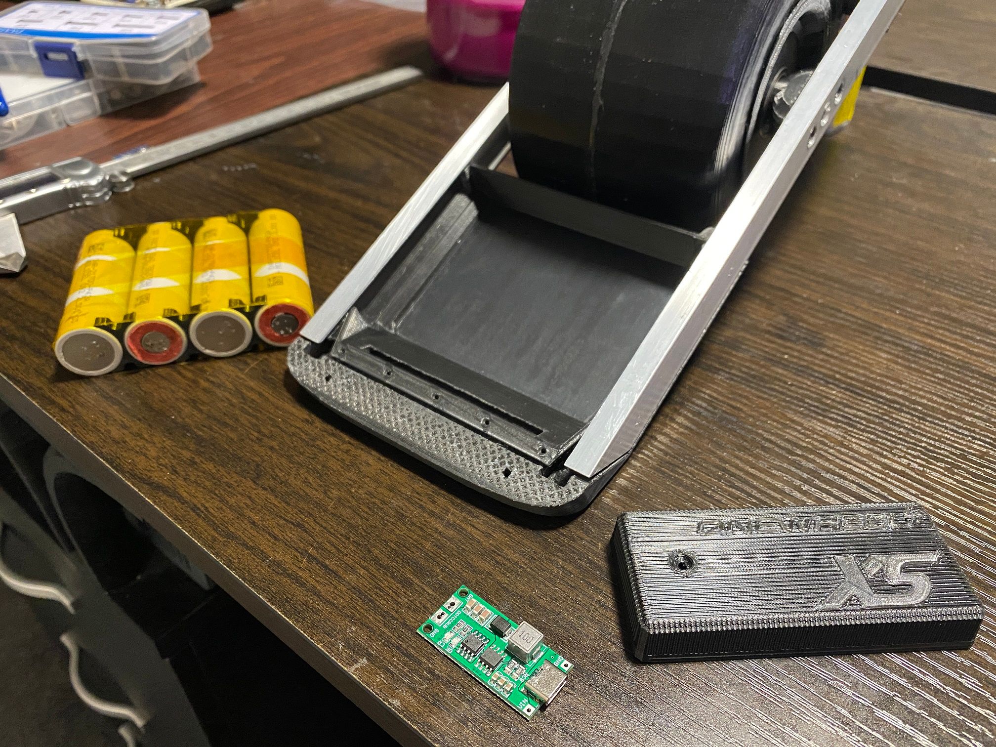
Everything is on a "go-slow" especially with work driving me insane. Feel like there's been enough progress for an update though :)
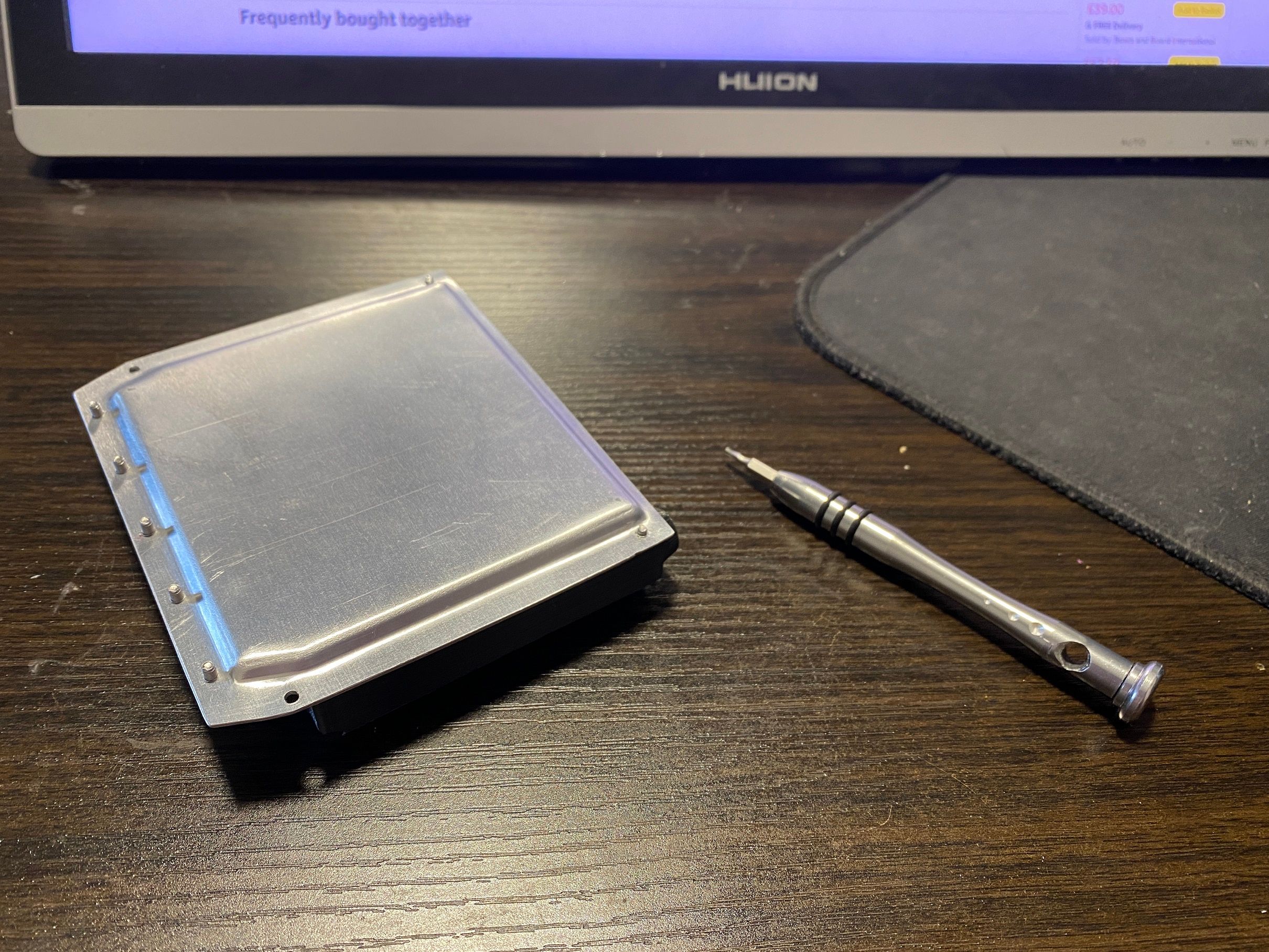
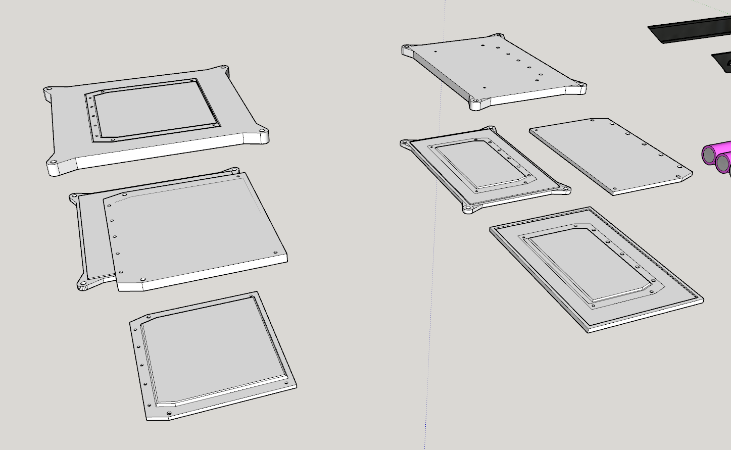
Battery housing lid before being trimmed to size.
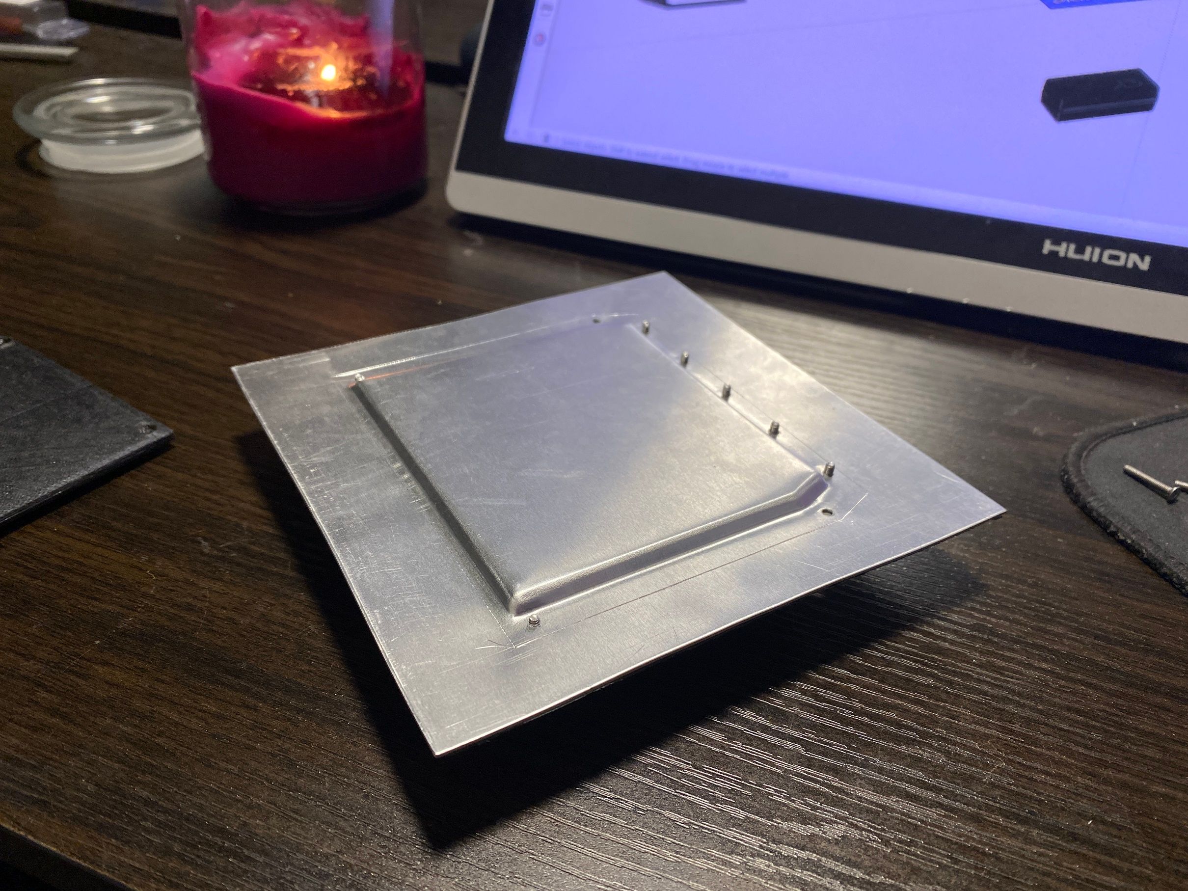
Cut the lid to size, still need to add the extended threaded sections since the 1mm plate is not going to last.
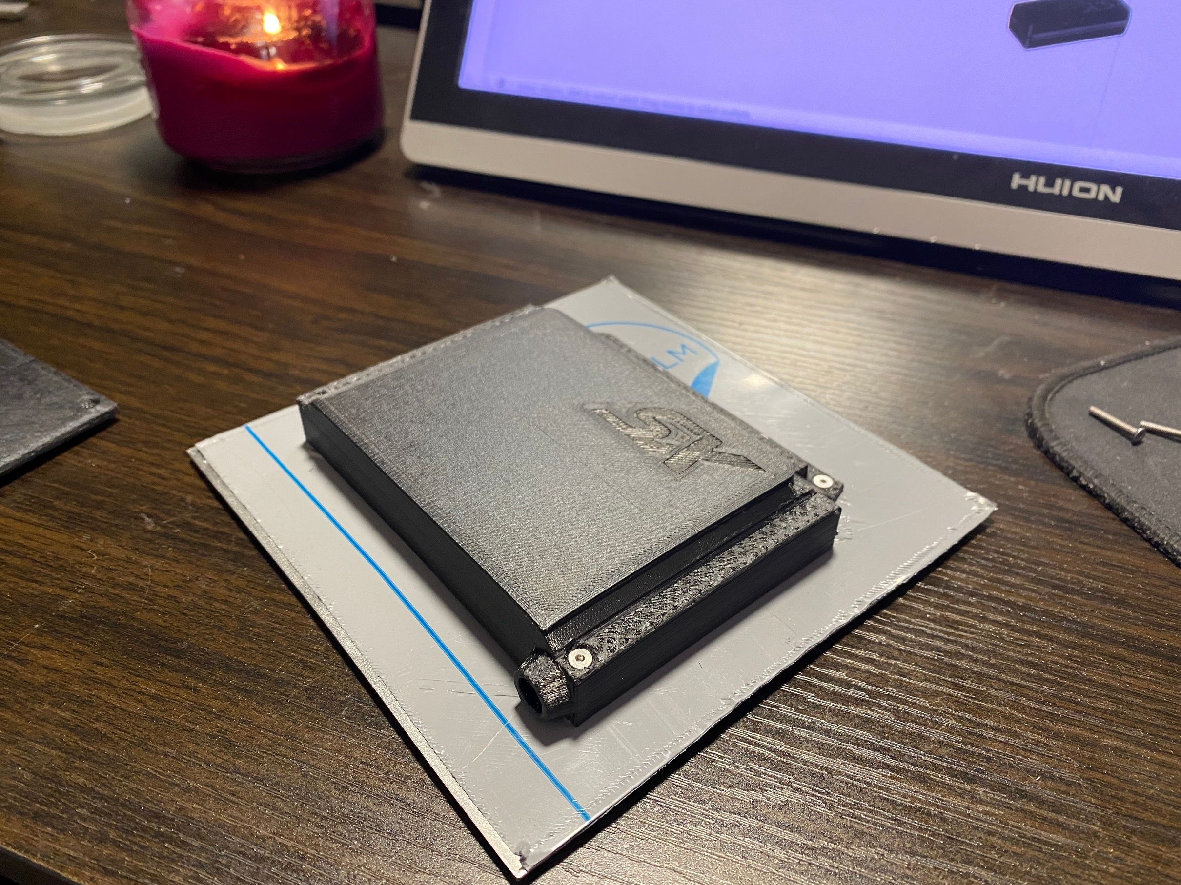
Cells fit, need to push up the middle of the lid as it's deformed in a tiny bit but other than that it all fits :)
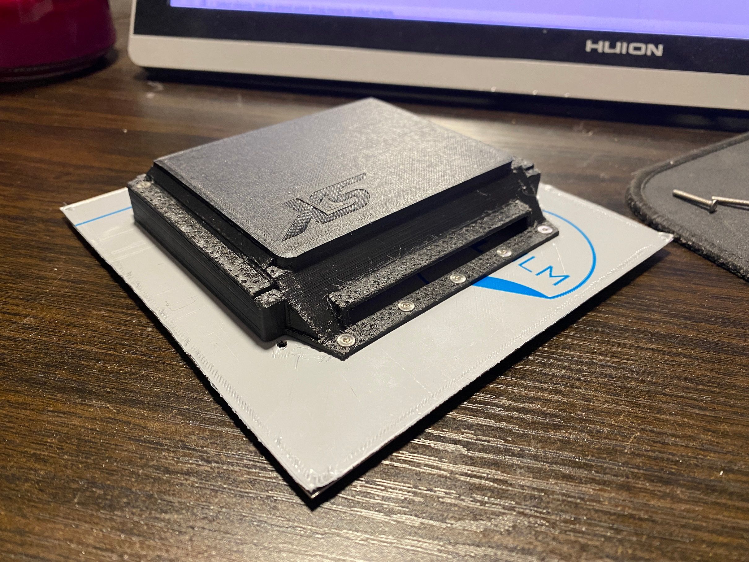
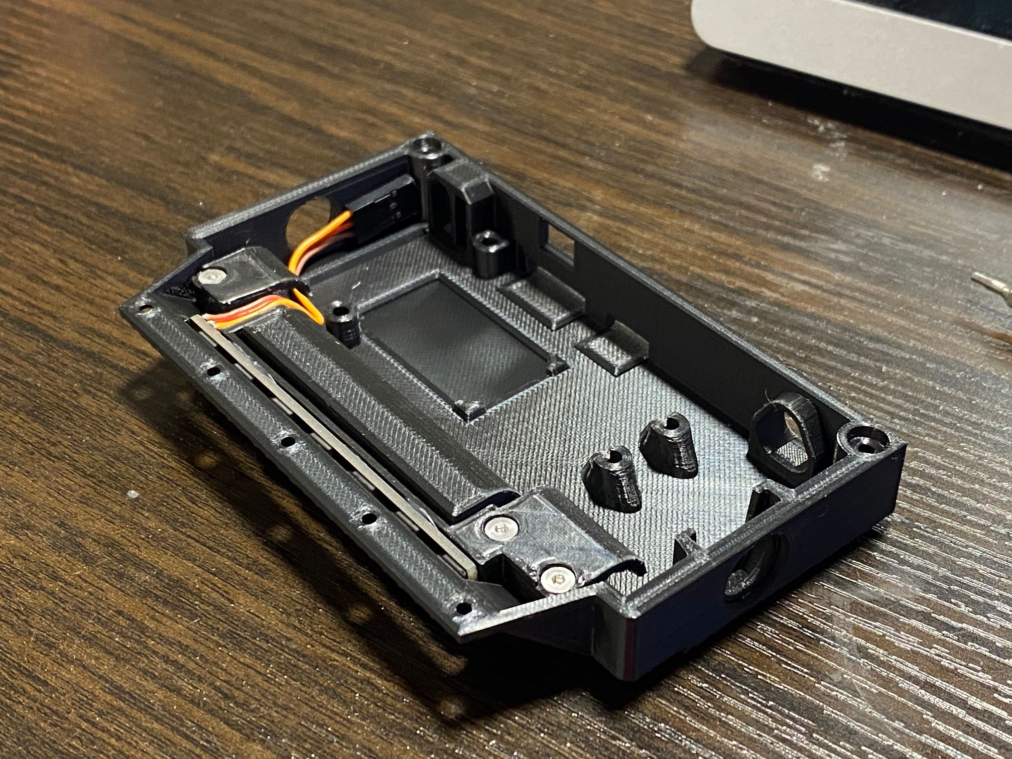
Made a new bracket for the capacitors that also will hold the front light bar. Got iPhone vibes from this part. Anyone that's taken apart an older iPhone and seen how things like the speaker look with the long tiny plastic brackets will know what I mean.
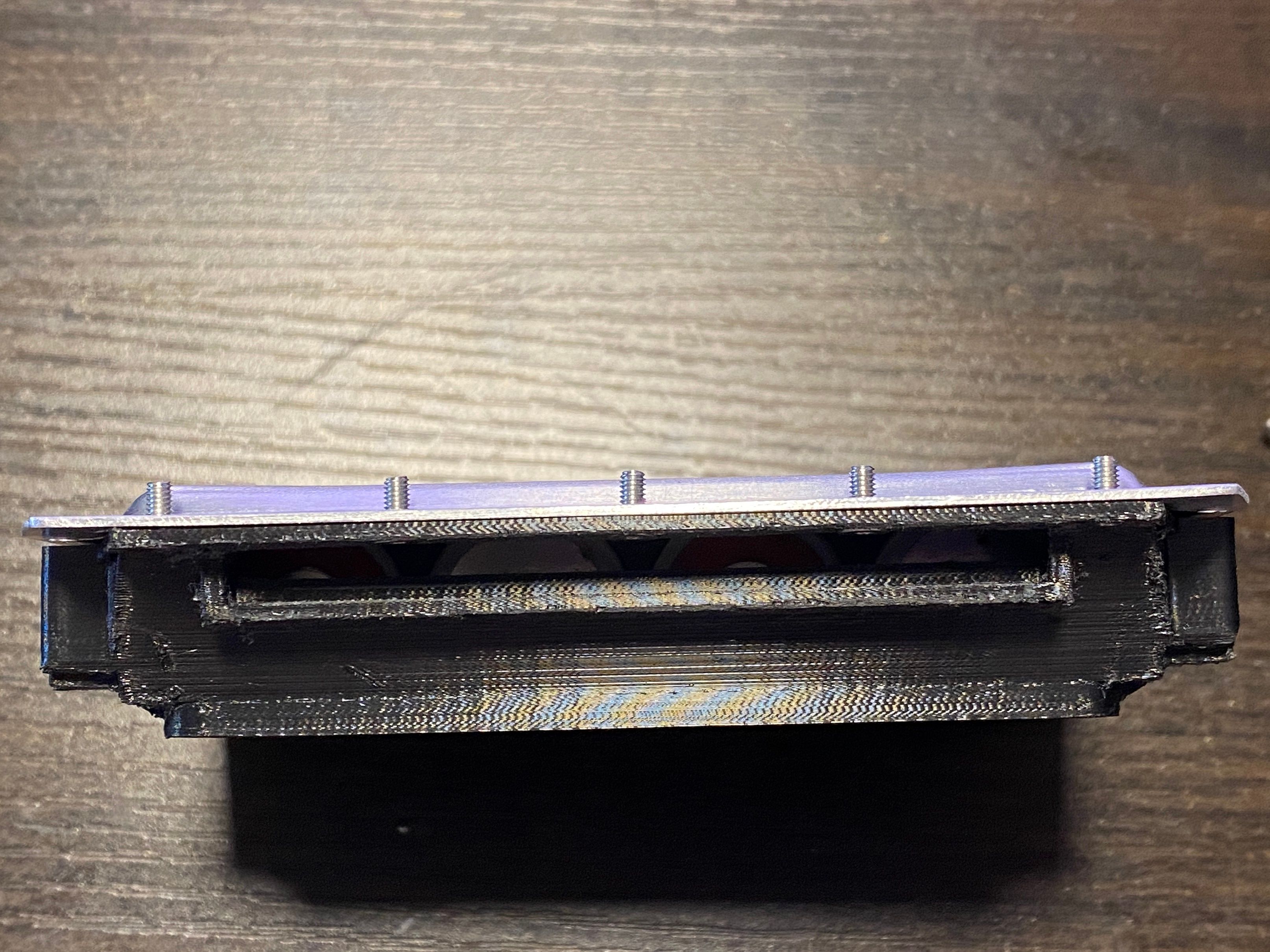
Unfortunately there is a 0.5mm clearance issue with the LEDs so it's hard to remove for now so I'll redo the lower controller housing to accommodate this.
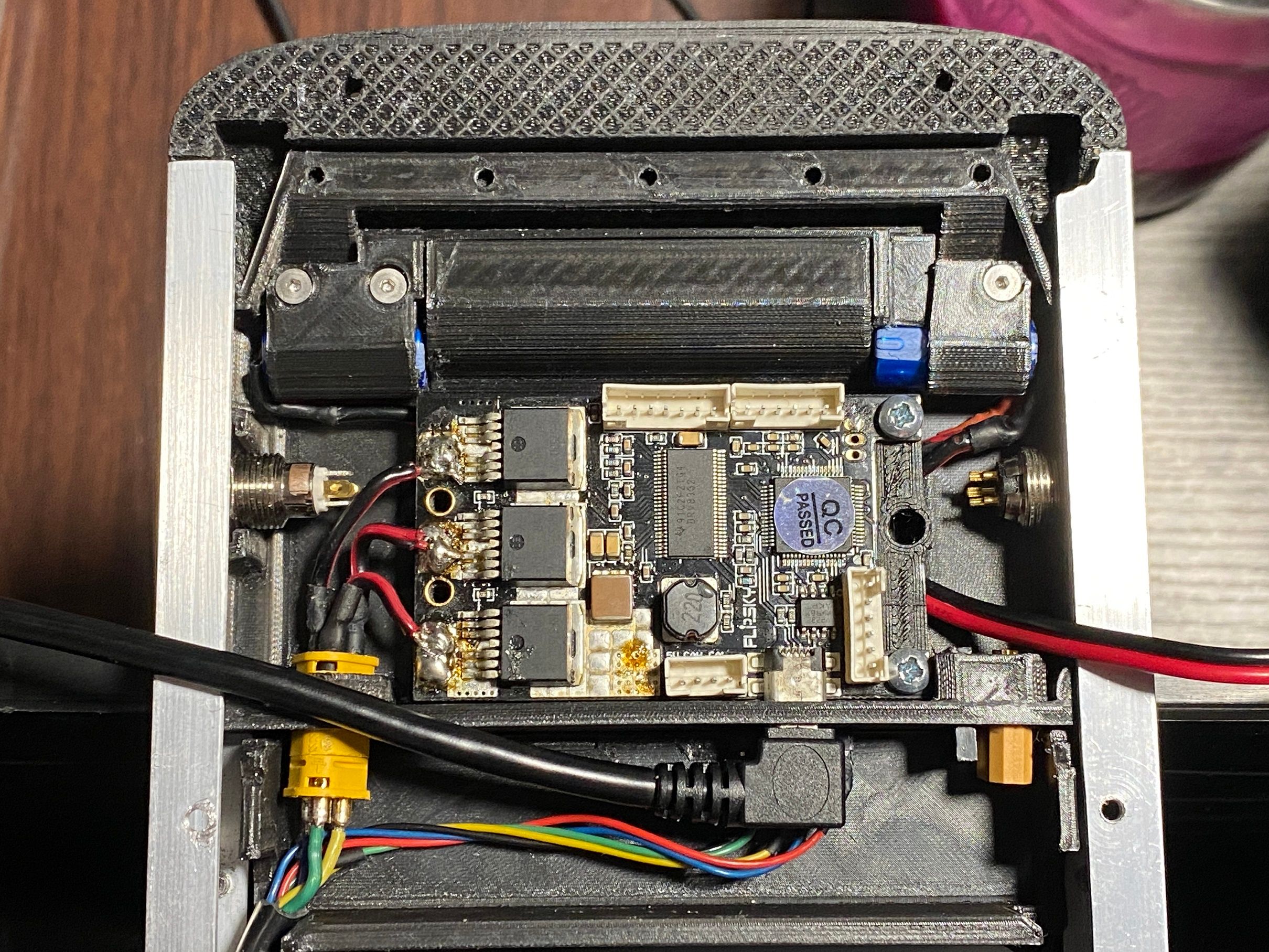
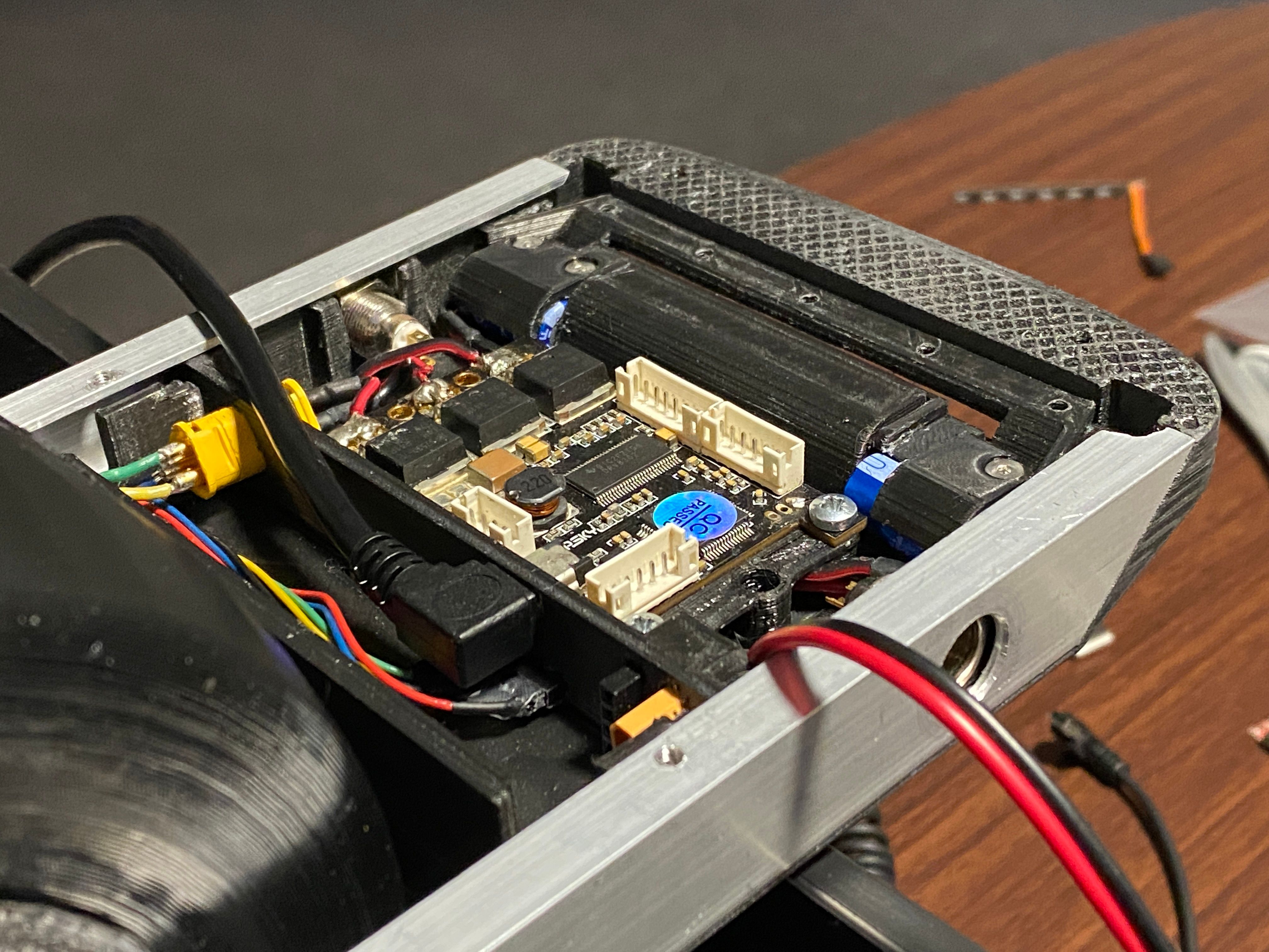
Finally it's come time to test the electronics... D:
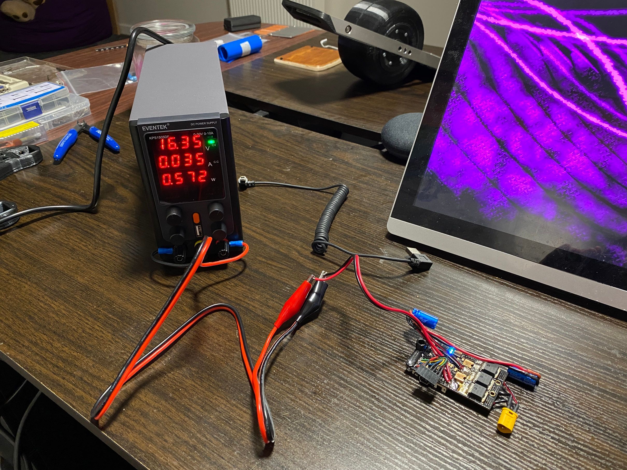
So far so good, no fire. Set the PSU to around 16v (4s) and only a max of 5amp rather than the full 10amp this can do. Time to mount it back in the XS and test the motor.
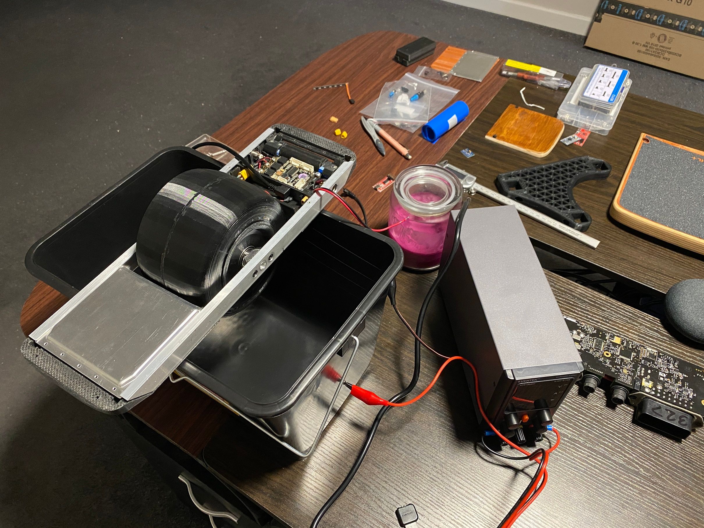
Time test see if it spins (sorry for the crap footage, the lighting mixed with a smudge on the lens makes it look hazy AF >.>)
It works~ :D
Rattly but works. Need to braze the axle bracket and rail together which will stop that since those are loose and definitely the cause of it. To be fair it only does it when spun up max speed (under current settings) so I'm happy with how it is so far. -
@lia I really admire your work, amazing attention to detail!
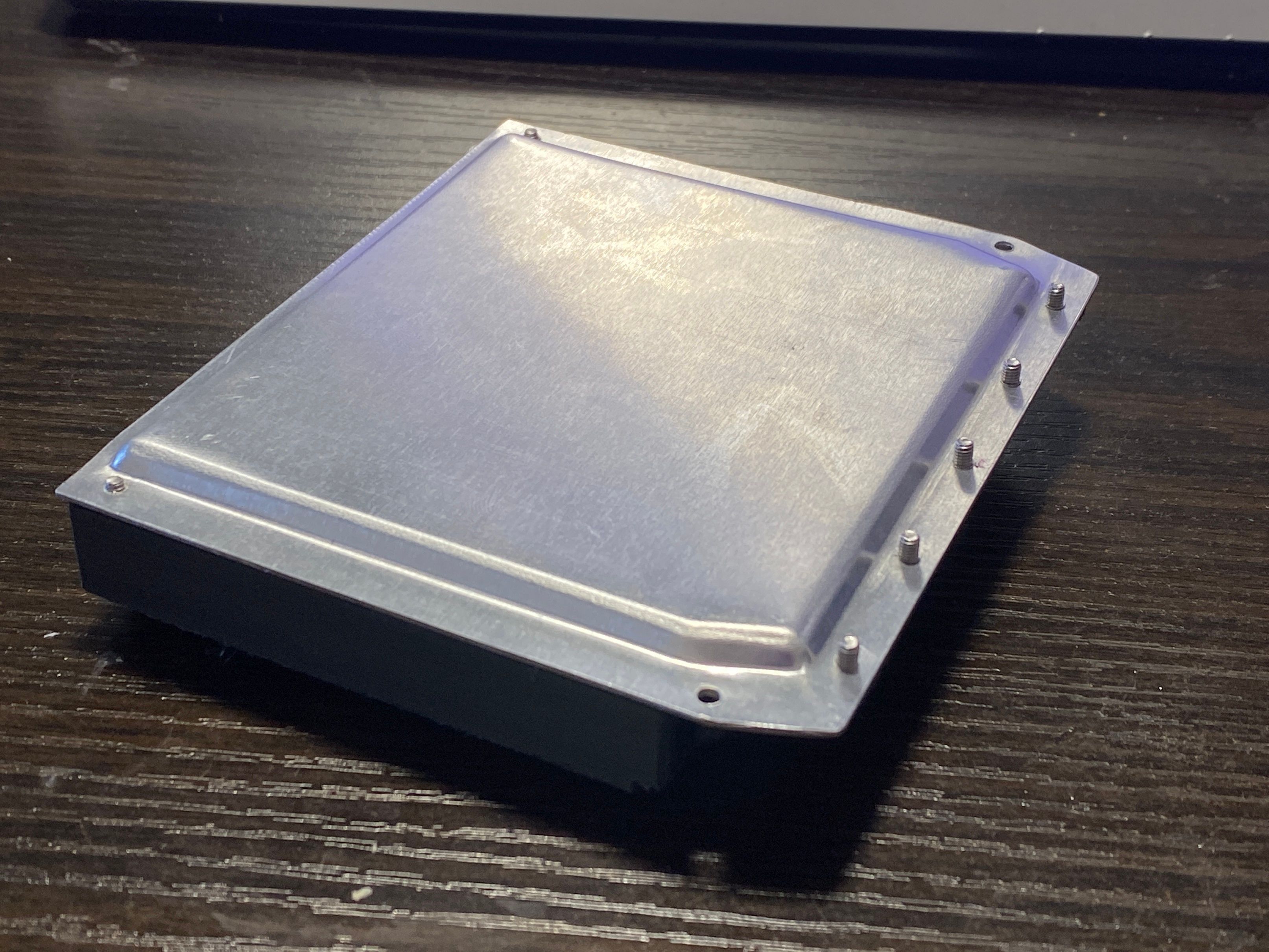
How did you fabricate the aluminum top plate ? Looks like it was pressed out with dies. -
@lia said in Onewheel XS:
So far so good, no fire.
This would be the pre-pre-alpha test . . . Good job!! ! :D
-
@lemur Thanks :D
You nailed it, made 2x 3D printed plates to encase the 1mm thick sheet then over several repeated sessions of crushing it in the vice it got the shape from the dies. Once pressed I drilled through the guide holes then used a final template to cut them on the mitre saw.
Controller was easy enough since I made that one correct to scale so it's barely raised. Battery side though I gave myself 3mm extra to work with since those cells stand no chance otherwise.
@OneDanGT Aha true xD Honestly was shocked nothing went pop like the caps.
-
@lia That's great engineering!
-
Oh, my god, is being a long time since I haven't seen that thread.
Lia, you are completely crazy!! You made it work!
So time consuming... this is just too much... Is not that I don't value what you did, which is superb. But your abilities deserved something you could ride ;) -
@ed_co Oh I'll totally ride it if not just for the humour of it :)
Just have to find the drive and brain power to figure out where to go next to finish it. The programming side and hooking up the gyro is daunting but is really the next step I should be taking.
-
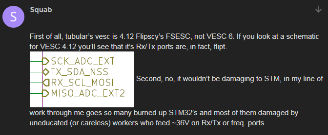
Wanted to get the gyro wired up but hit a snag where connecting it drops my usb connection to the VESC. Ignoring the Arduino and passing the gyro data straight into the FSESC to interpret since it has it's own balance app built into the VESC tool :)
I'm probably wiring it up wrong since the pinout for RX/TX on my FSESC seems to vary a little depending on whose documentation I'm looking at.
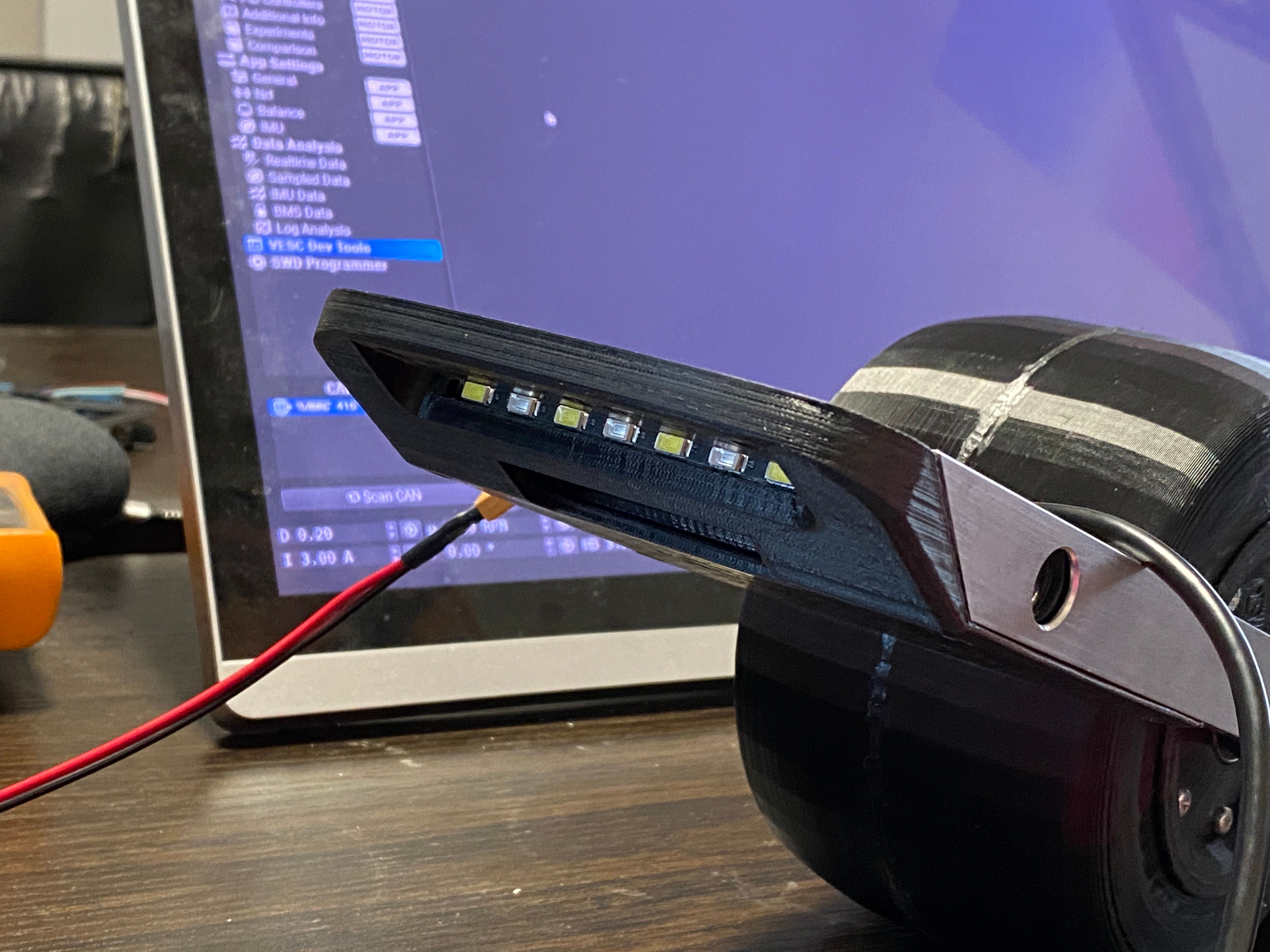
So in the meantime I've reprinted the controller housing to accommodate the LED bar a bit better.
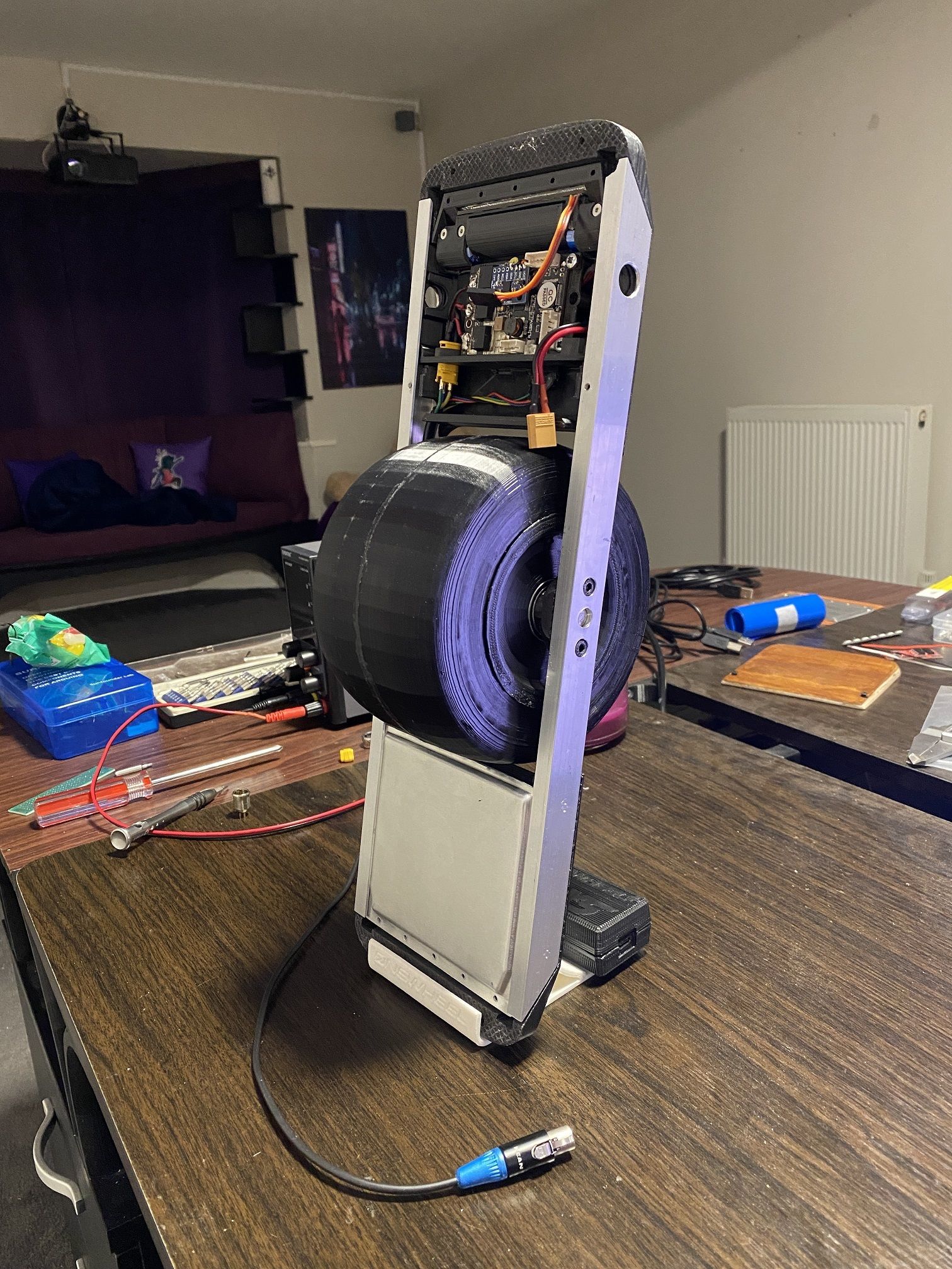
Love seeing this thing move so decided to dangle the USB cable over and took it for it's first float. Still hooked up to external power of course. Last thing I want is to have a fault that sets 4 cells on fire D:
Motion is super rigid because the keyboard controls are full backward, -1mph , +2mph and full forward (under current restrictions programmed for now).
Still pleased with the amount of torque shown without even touching a single amp (I should be allowed up to 30A burst and 20A continuous).
Once I get the gyro hooked up I'll look at doing a balance test with my hands before working on making it structurally solid enough to definitely hold my weight.
-
@lia Hilariously awesome watching the baby learn to float!
GTS XL > GTS > GT > Pint X > XR > +
-
@onedangt IKR. So adorable watching it flop around.
You can tell which side I biased the cells in the battery housing by how it naturally wants to turn left. -
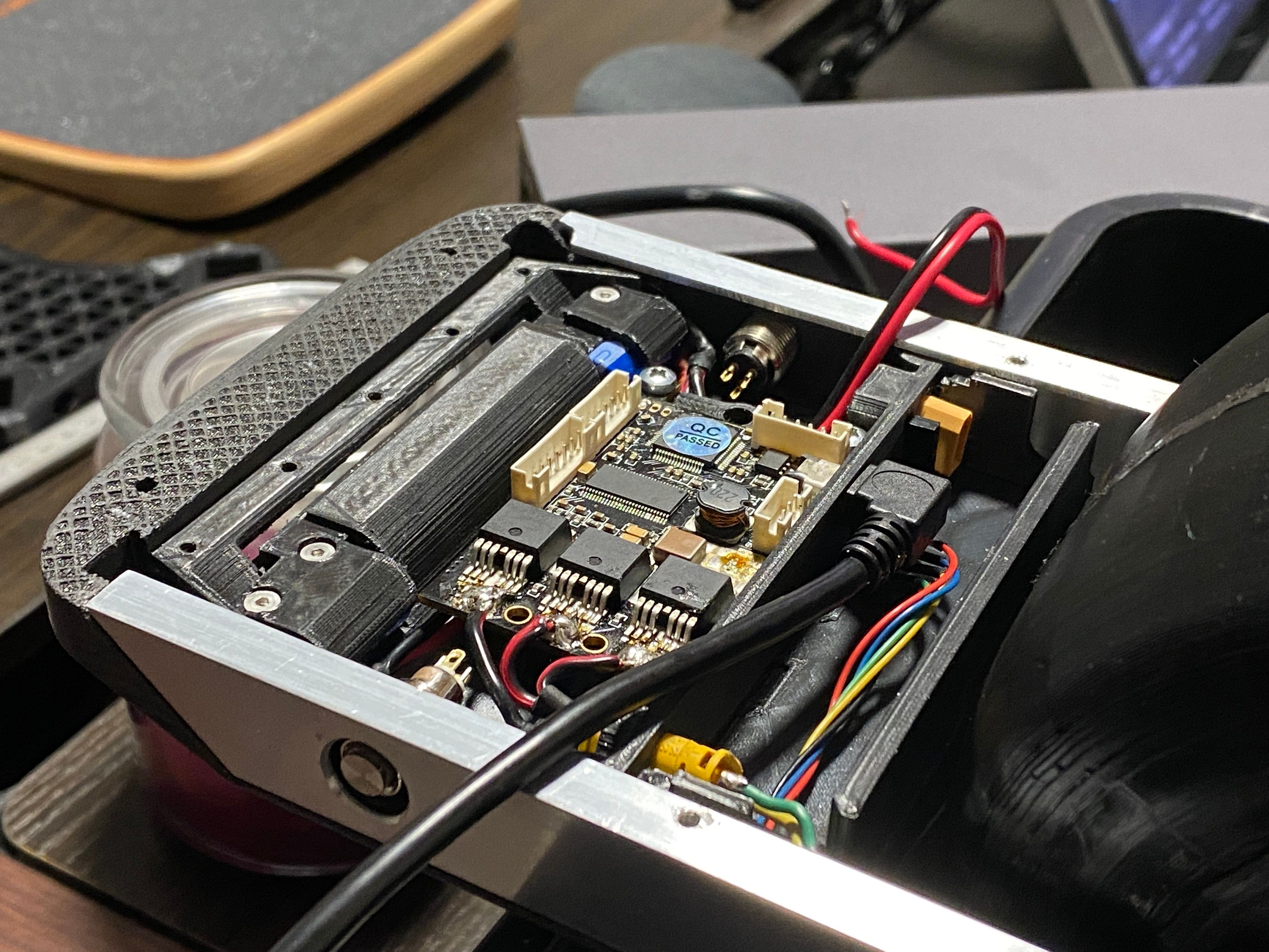
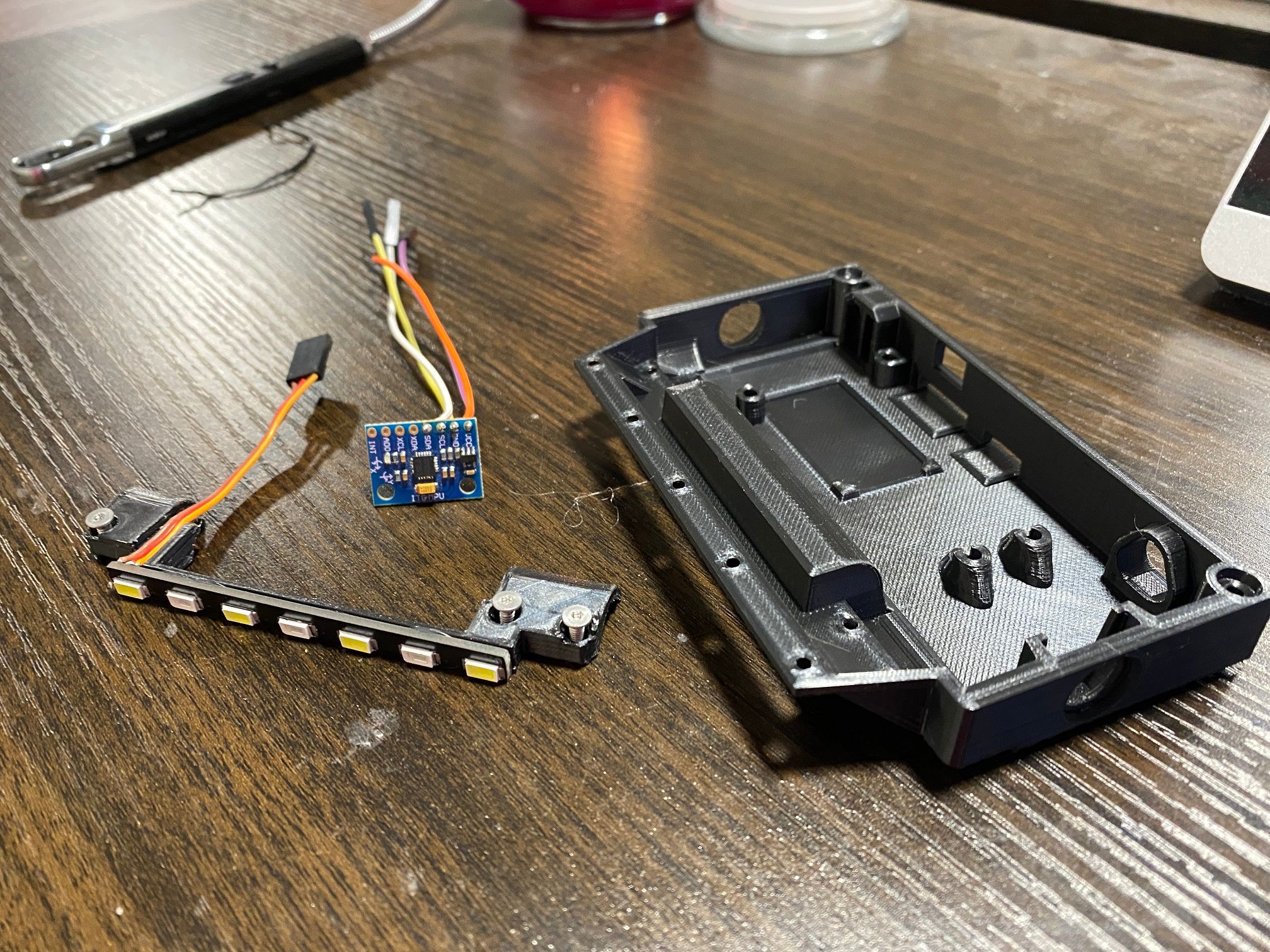
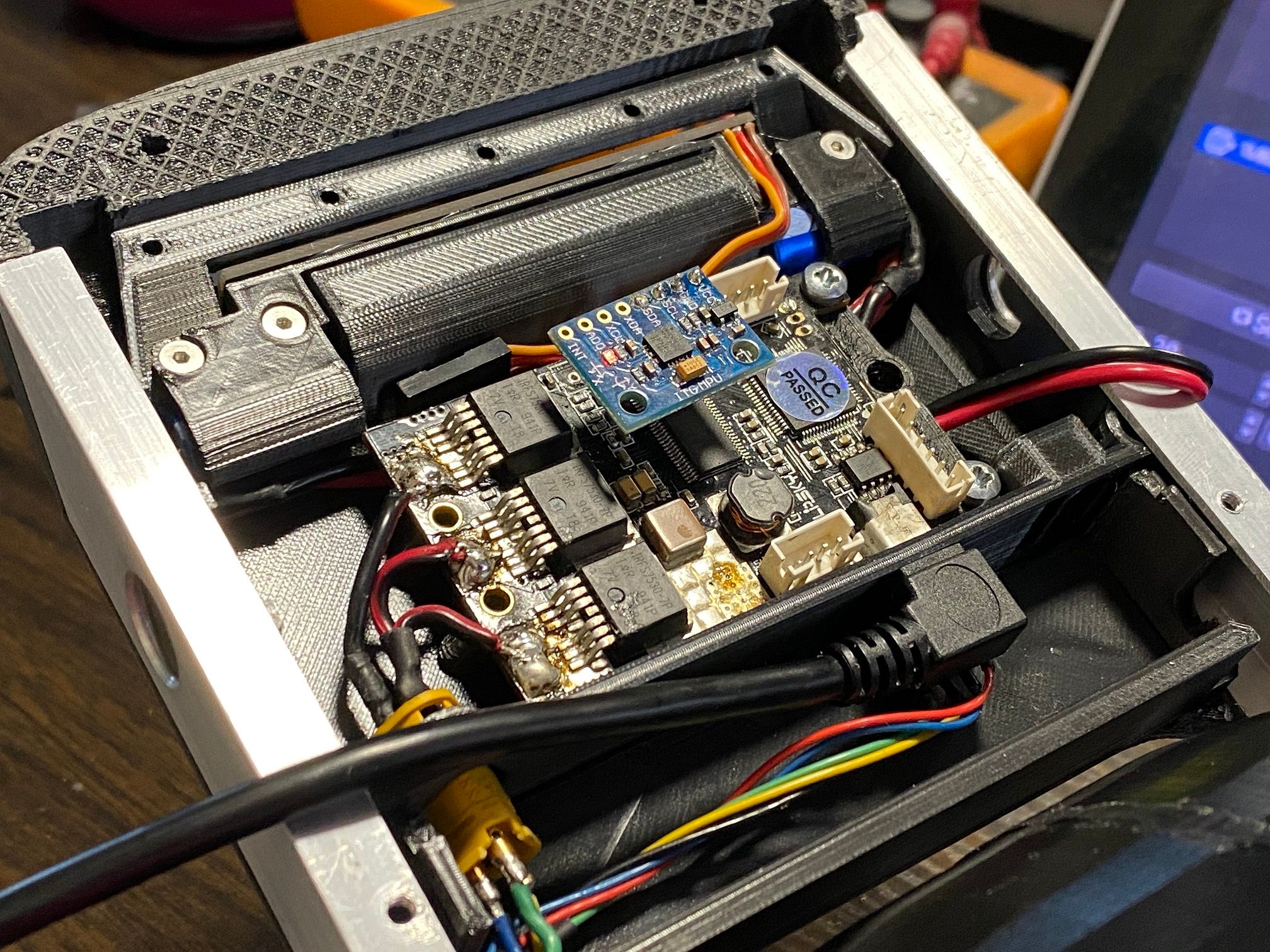
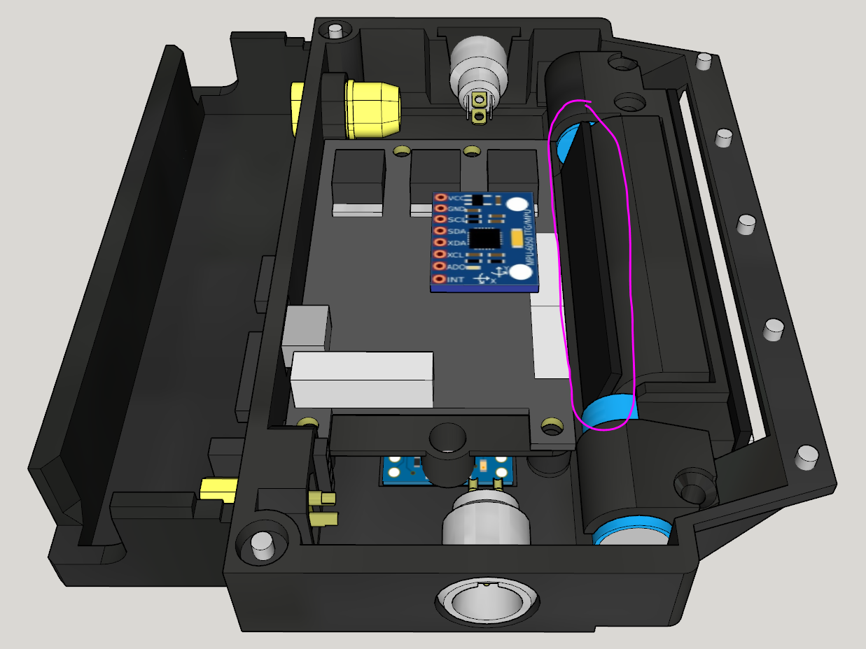
Got the IMU hooked up "properly". Soldered it directly to eliminate any dodgy data. However the VESC still cannot communicate over the I2C line (SDL/SDA) to the IMU.
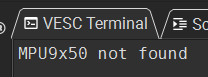
Not sure if it's just bust or I'm missing something so will try testing it on a spare Arduino another day to verify.
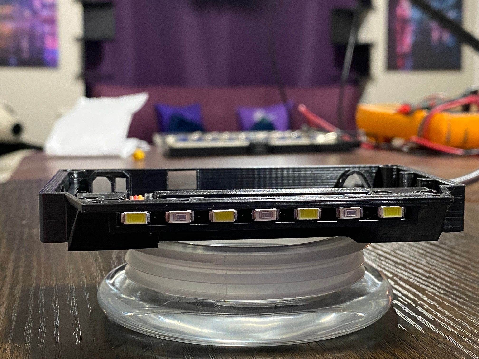
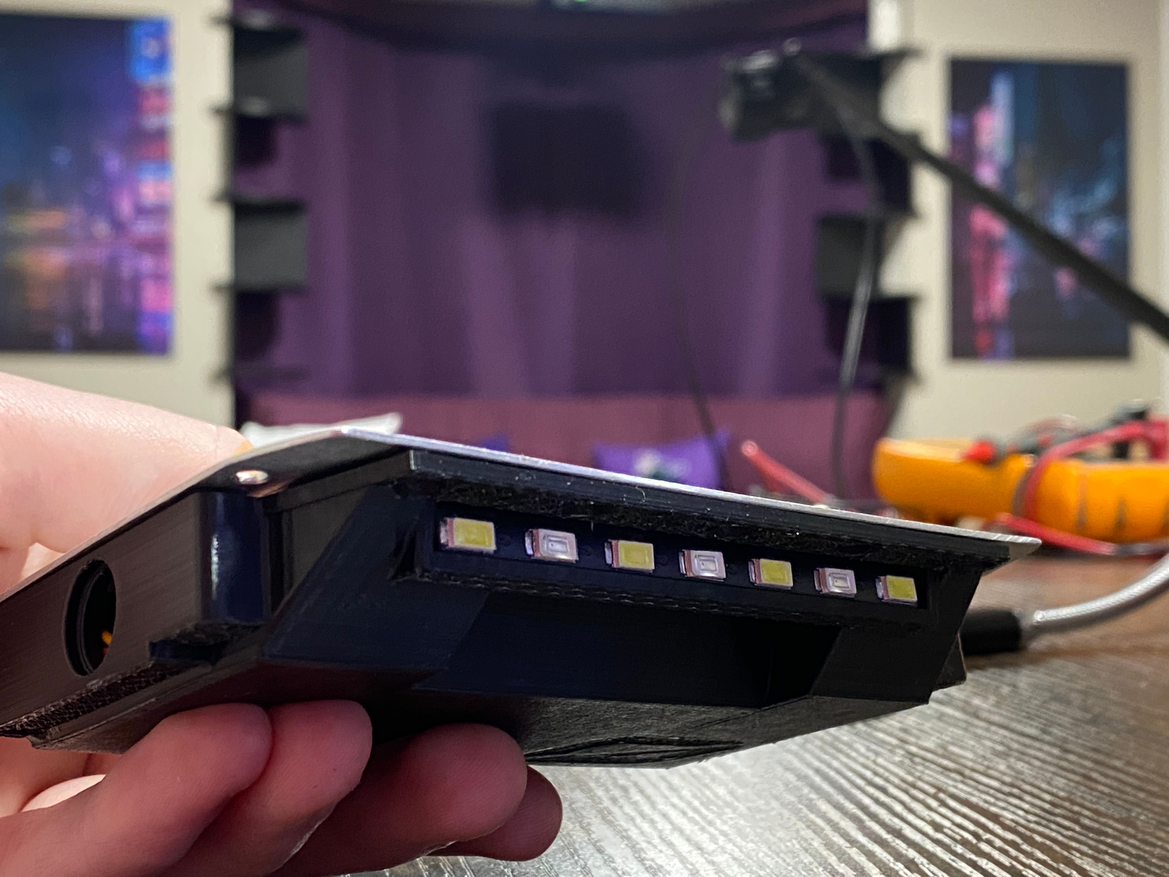
Also thanks to the housing redesign the LEDs fit nicely now.
Will have to find a way to control them still, might still use an Arduino to read the hall wires from the motor to change the lights. Will need an external mosfet to control that since the tiny Arduino I have will fry if I try to power them off it. Already tight for space and still need to implement a power circuit to toggle power depending on the button's state up in the controller. I'll likely put that near the BMS since there is some room there and makes sense.
Learnt a bunch from fiddling so far although my squishy head hasn't made complete sense of
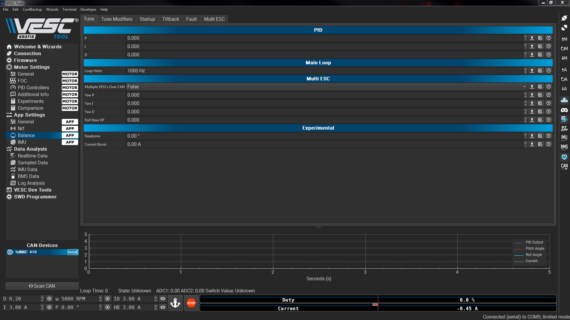
anymost of it. Updated the firmware and now most of the balance config is available. Also swapping the "App To Use" setting to enable balance settings causes the manual keyboard controls to act real weird, thought I busted the settings at first.After adjusting limits though it runs smother still without being secured properly.
.
Edit : Looks like my little MPU-6050 is dead, wild since I've had it sitting unused for like half a decade in my Arduino box. Used some test code and can't get it to spit out anything. Ordered a new one to come tomorrow :D
Edit 2 : New one showed up and worked straight away on the test bed so will look to plop it into the XS tonight after I've finished melting from today's ride.
-
They said it couldn't be done!
This is with P=1 I=0 D=0 for now.
Saw suggestions on the full scale to have P at 25 but when I tried that it attempted to take off before hitting the duty limit moments shy of screaming off the table.But wait there's more... I have invented Ghosting+
And this is with extremely limited "don't catch fire" settings. I still have to tune it! (and have it run off the internal battery)
Took longer than expected. Wired up the new MPU aaaaaand nothing. Turns out after an hour of googling I came across this gem.
https://electric-skateboard.builders/t/onewheel-build-guide/80129/449
THE DAMN PINS ARE REVERSED REEEEEEEE
After swapping those it worked. I did that on my old one but it was totally broke and didn't think to try on the new one >.>
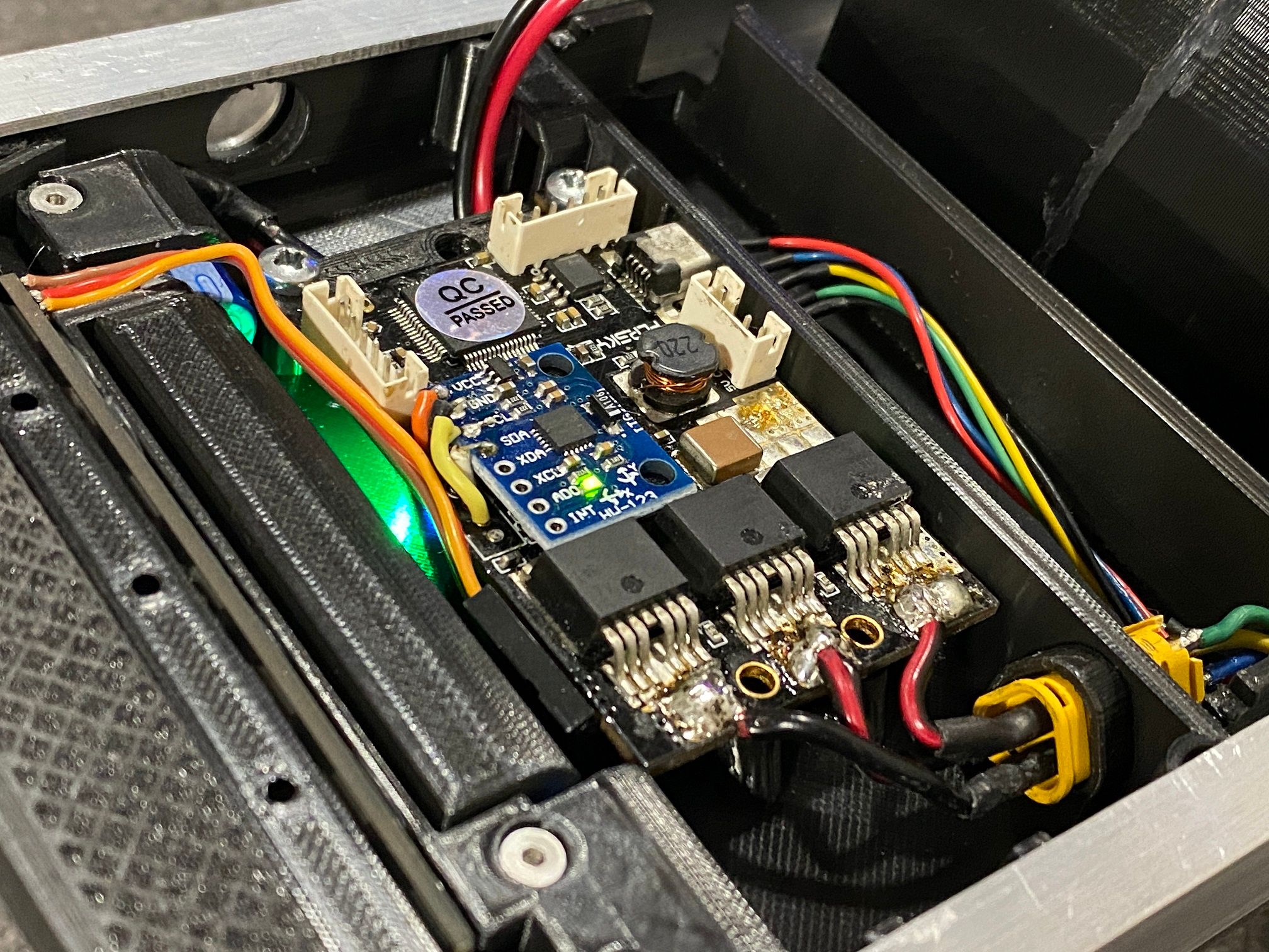
Sandwiching the IMU between a connector and mosfet is probably fine right? I added electrical tape to the bottom afterall which is the electrical equivalent of hiding under the sheets so the monster can't get you.Next up is building some footpads (that don't ghost). The 40x40 FSR's go for about £12 each which kinda sucks but if I want this done I'll have to buy them. It'll add a tremendous amount of rigidity to the whole thing and allow me to test ride it.
In the meantime since they might take a while to come I might look at hooking up the LEDs.
I definitely need to redo the tire. That TPU does not grip to anything well enough. Guess casting rubber might be my next best bet. Print a tire in PLA, make a mold around it then cast into the mold. Printing a mold makes sanding more difficult as I discovered prior to the TPU tire.
-
Seat belt/air bag occupancy sensors would likely be the cheapest foot pad sensor option. Short of build your own with alum-in-um foil and silicone to give sensor separation to prevent ghosting.
"... We've been trying to reach you about abandoning the OW as a platform, and convert to EUCs."
-
@samuraipunch I do have some of those car seat sensors recommended to me by @ed_co for a full sized pad but I'd need to cut them up to fit this 1/2 scale pad.
.
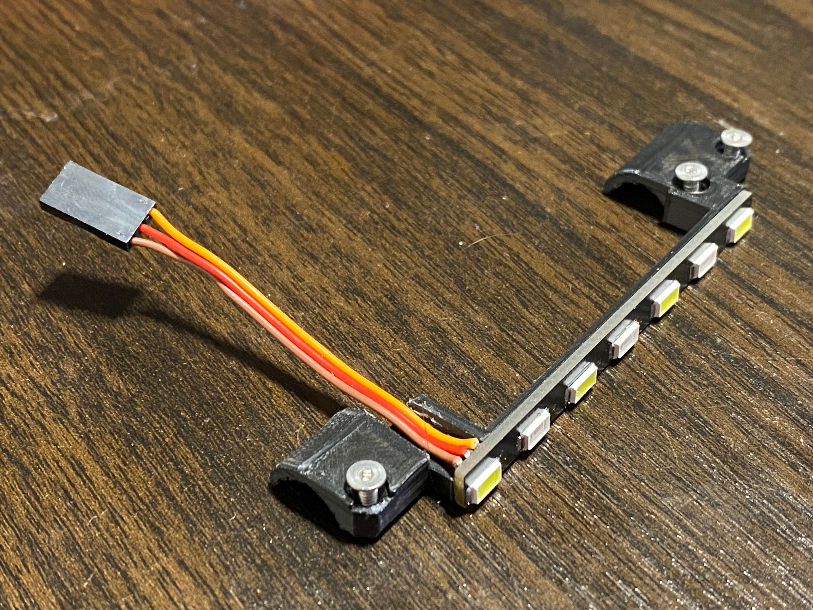
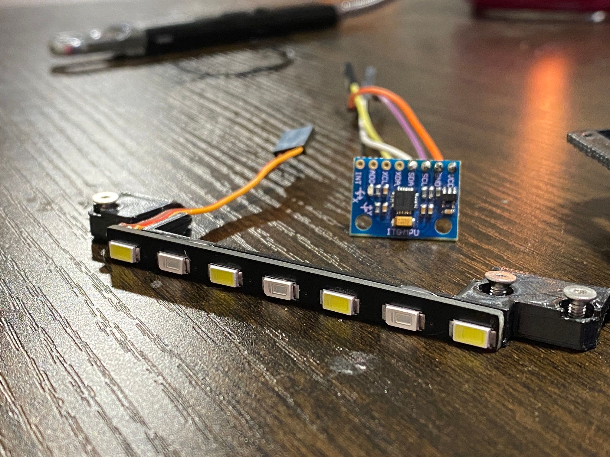
Edit 1 : Did some testing with the LEDs. Built the rear bar and found some PNP transistors that I could use to power these. Would use NPN but I used a common ground making it impossible without redoing the lightbars.
Also here's the power button using the same fade animation to test.
I'll need to build a little 3xPnP transistor board to power this lot. 1 for forward, 1 for reverse and 1 for the power button :)
.
Edit 2 : Designed a small PCB to drive the LEDS from the Arduino Pro Mini tucked under the FSESC. Getting real dense in this controller box. Will need to also run split connections off the hall sensors wires into the Arduino to figure out the rotation to change the lights but that's for another day.
Also I printed a half scale stand ;)
.
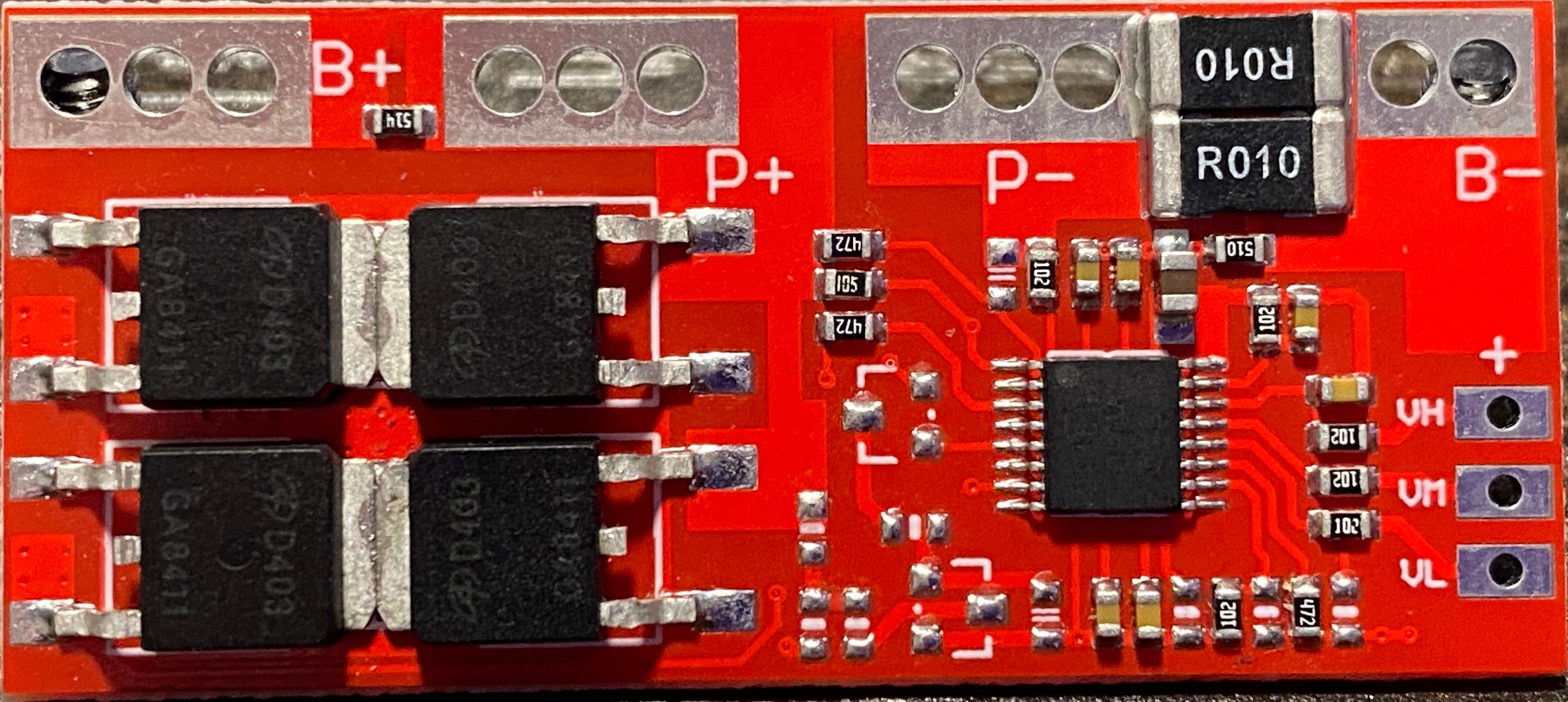
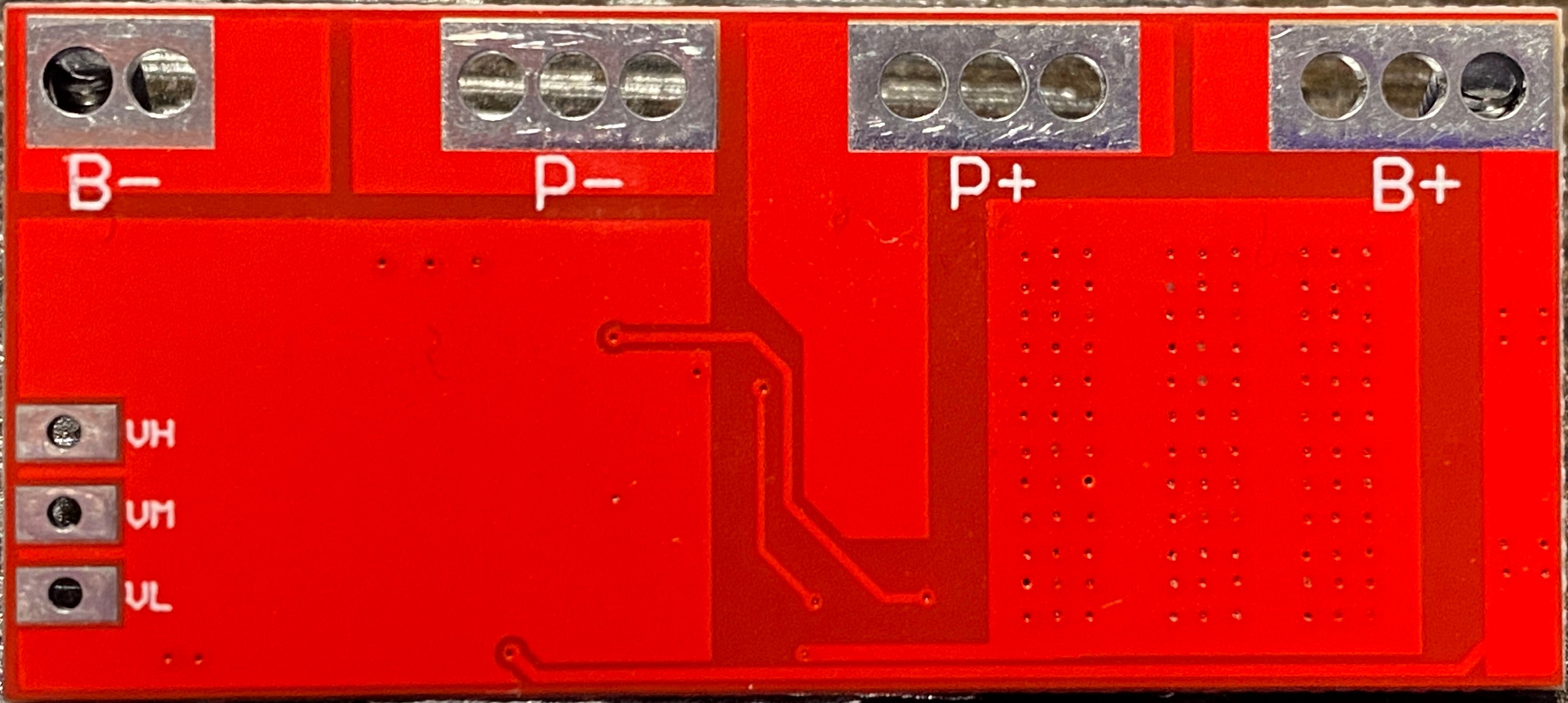
Edit 3 : I think I found a simple way to add a switch to the BMS without using external mosfets.
Wanted to use the fets on the BMS but couldn't figure out what I might need to do. Found the datasheet for the protection IC and think I might be able to simple cut the trace leading off pin 3 and run the switch wires between them.https://www.ablic.com/en/doc/datasheet/battery_protection/S8254A_E.pdf
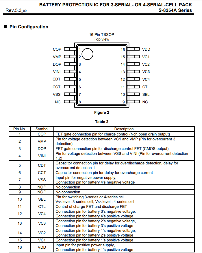
Pin 11 also controls all apparently but I don't want to require the switch to be on to charge.
Not sure if this will work as I intend, after lots of research plenty have wondered about adding switches to larger BMS's and most seem to give up, use an anti-spark circuit or wire the switch into a thermistor to cause a fault and disable it. None that I can find toy with just intercepting the gate for the output fets. I can only assume for good reason but I want to see if it will work :)