@rc It will take a while before your muscles in your feet get used to onewheeling you are using muscles in your feet you don't normally use to begin with try short stints but try and get regular sessions and build them up
Group Details
DIY
DIY Board Owners
Member List
-
RE: Turn leftposted in General Discussion

-
RE: Turn leftposted in General Discussion
@rc honestly, i think it's just practice. foot stance might be part of it, too. Lots of riders i see put their feet at each end of the board, but that seems too sketchy and more work to me. I ride with my feet close to the hub, so it's just a quick ankle flex and a bit of a weight shift for me to turn. sharper turns i think i do some sort of arm swing/shoulder & torso twist to accomplish it, but otherwise...

-
RE: Pint or pint X for 8 years oldposted in General Discussion
@bigorne for your son a regular pint would be more than enough. You may need to experiment with his footwear so the footpad detects him as some shoes with less weight is hard to detect.
For yourself a PintX would be great. You should both get similar enough range currently to enjoy rides together :)

-
RE: Drum & Bass On The Bike - MILTON KEYNES 2026posted in Wall of Stoke
@franko Defo go next time! I'd love for something more frequent at a smaller scale.
-
RE: Drum & Bass On The Bike - MILTON KEYNES 2026posted in Wall of Stoke
@lia wow, what a great event! we have a similar event here on wednesdays, but it's nowhere near as huge. i keep meaning to go...
-
RE: Drum & Bass On The Bike - MILTON KEYNES 2026posted in Wall of Stoke
Just saw myself and a few friends in another vid ^-^
-
RE: Drum & Bass On The Bike - MILTON KEYNES 2026posted in Wall of Stoke
@scabaa Just means we need to convert them 💅
-
RE: Drum & Bass On The Bike - MILTON KEYNES 2026posted in Wall of Stoke
@scabaa To be fair some of us had just come from a group ride in the morning but a handful of others showed up that weren't on the initial ride.
I wonder if Dom would do an IOM DNB ride? Like that'd be so cool if he did.
-
Drum & Bass On The Bike - MILTON KEYNES 2026posted in Wall of Stoke
2 weeks ago me and a few friends attended a group ride unlike any other.
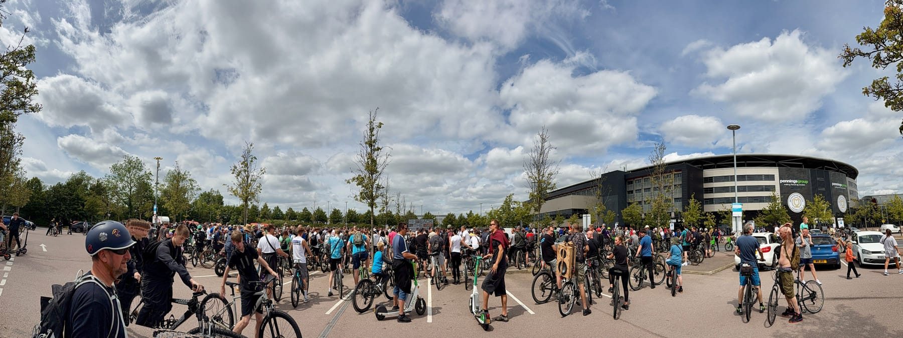
Yes mostly bikes but we had a few onewheelers come to represent.
I think I counted at least 10 Onewheels but there were so many of us DnB heads I can't say for certain.
All I know is we shut down MK that day!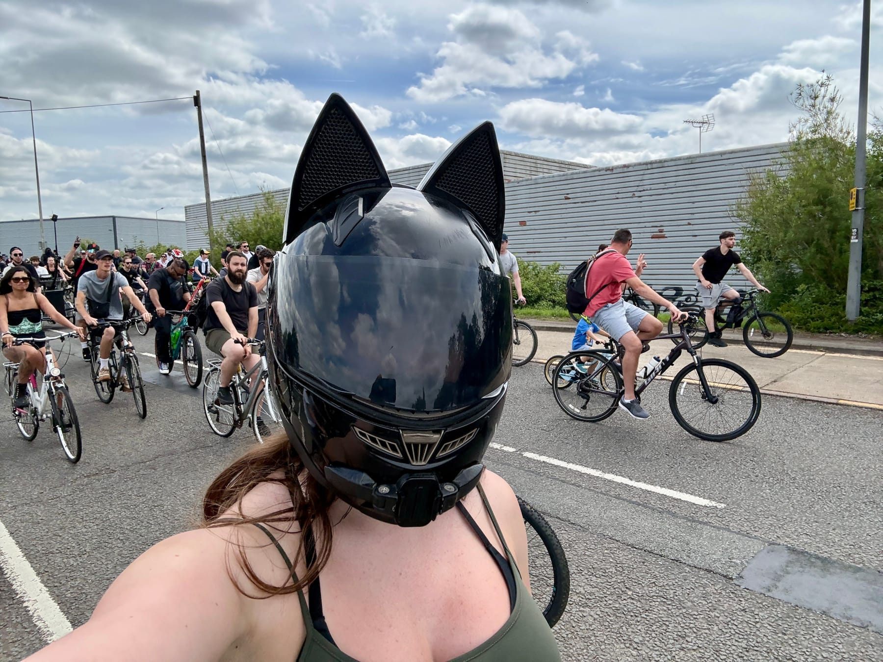
I decided to get up front for the first bit and get some space to carve. Back in the main pack was very closely packed and a little hard to navigate with all the handlebars poking me in the front and regular bottom 🍑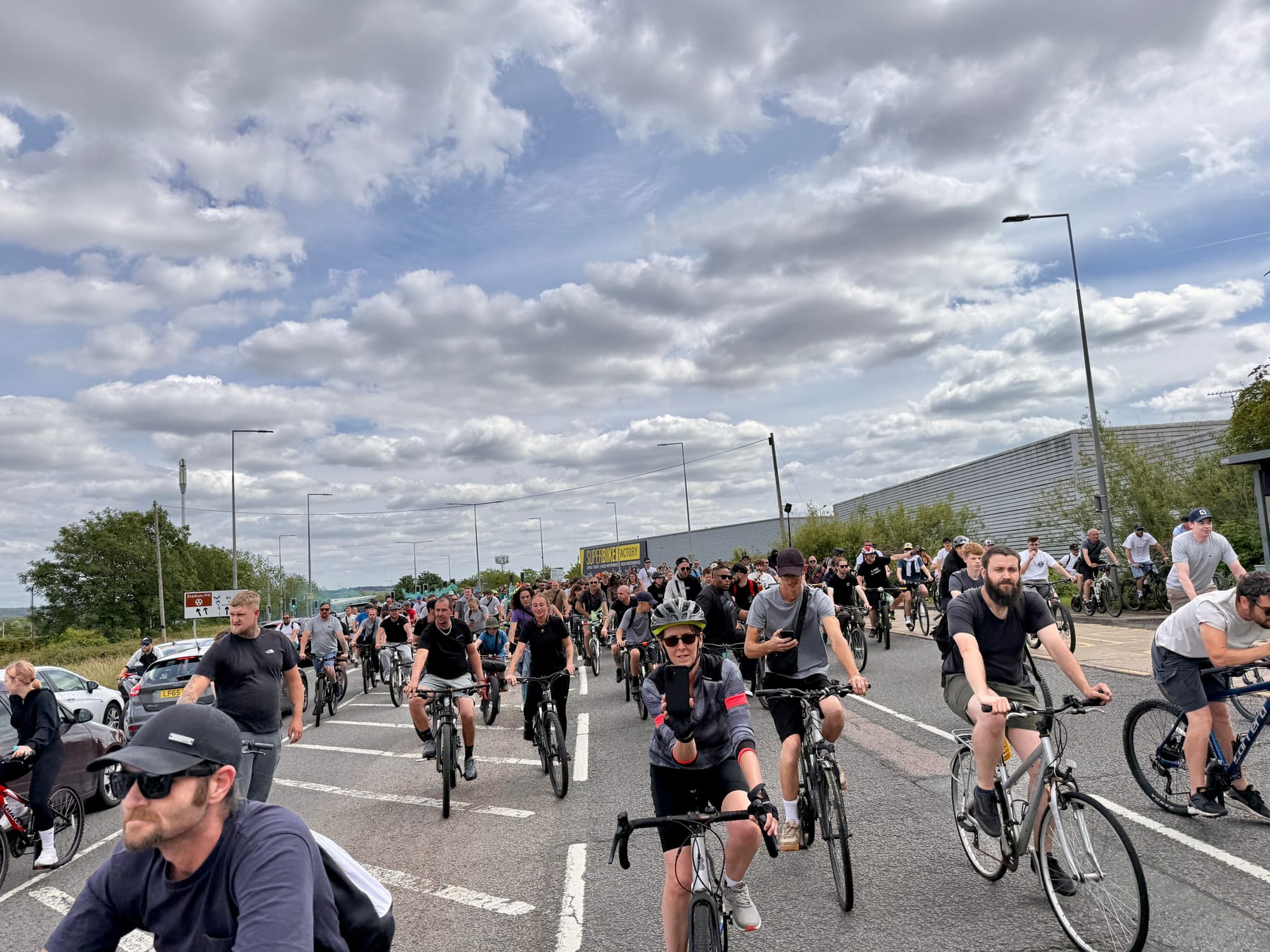
It looks mental now but things only got more insane as we rode as a huge pack adding to our numbers the further we went.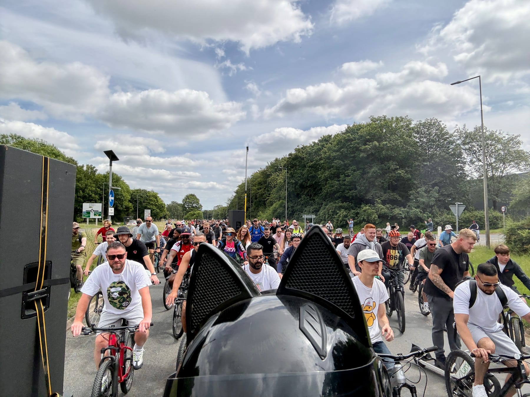
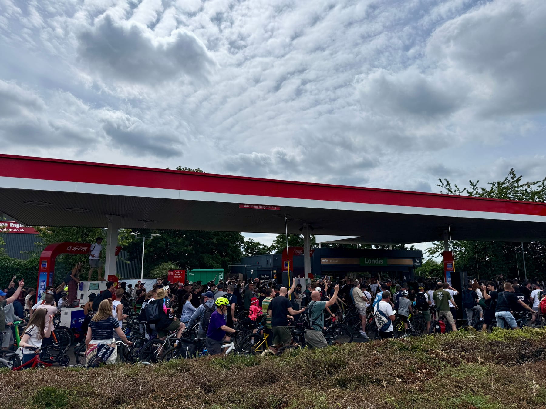
Getting in around the speaker bikes was where you wanted to be. Getting a full body dose of bass. Literally making my entire body shake at points!Then we got to the petrol station. Apparently this was the main attraction last year and this year did not disappoint.
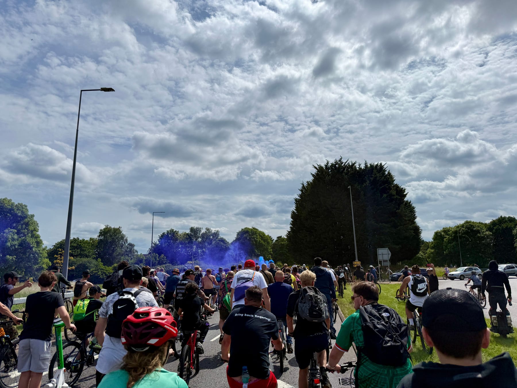
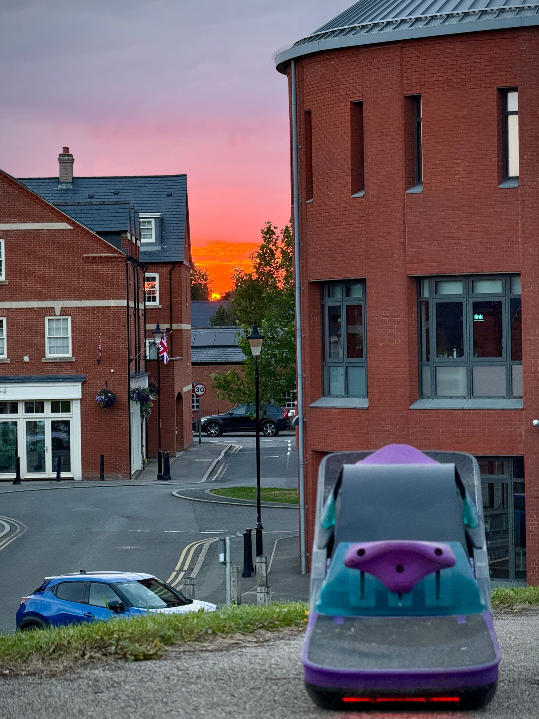
@Beardonaboard just cruuuuising through the crowds outside MK Central Station.
And then helping out a skater get some speed up the hills. With his board being an absolute tank he had no issues towing.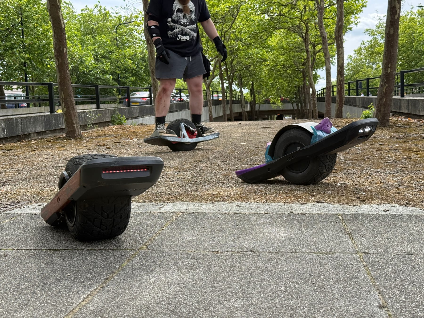
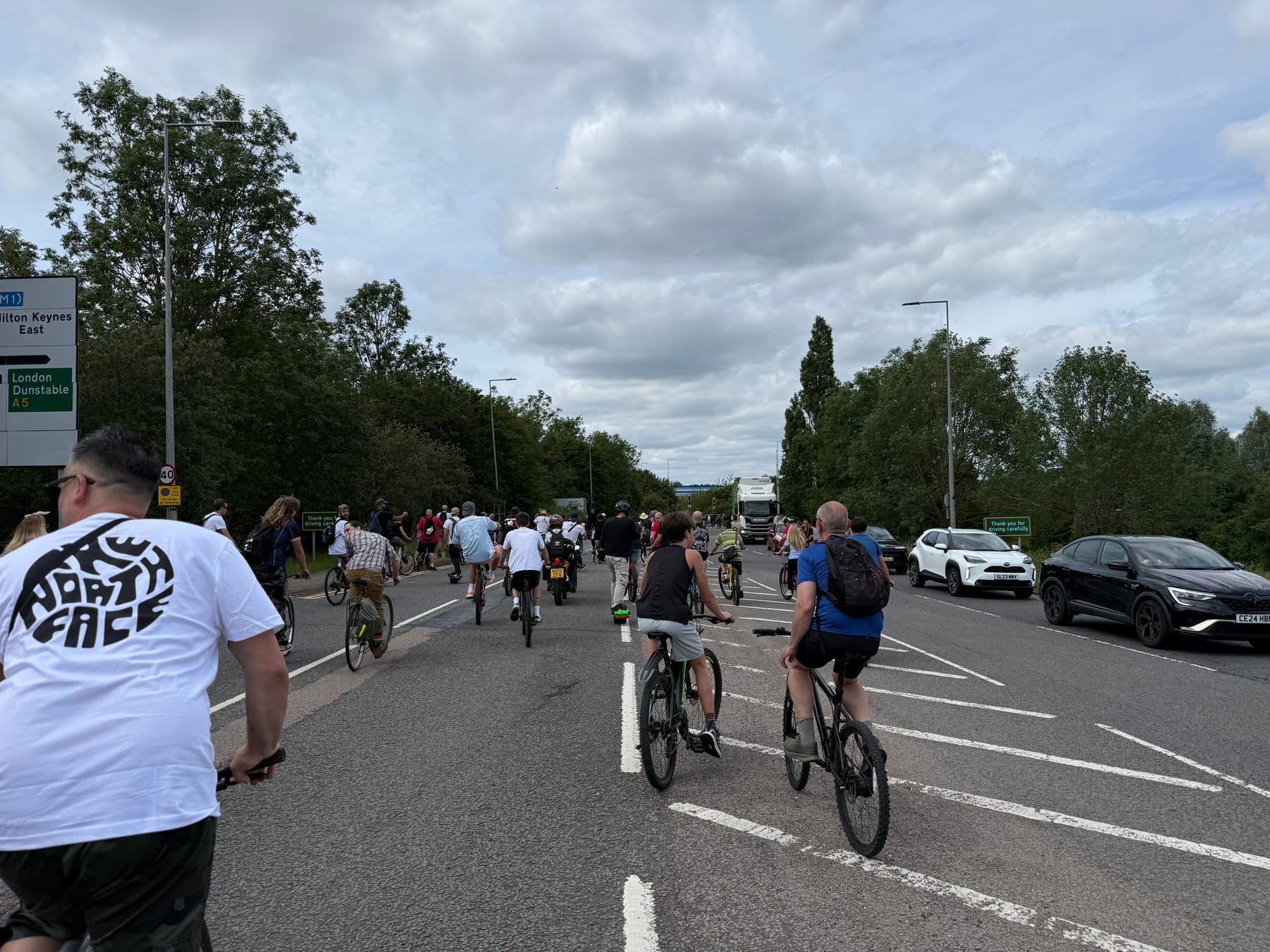
Midride me and gang got to shoot off ahead to get a little break from the crowds.
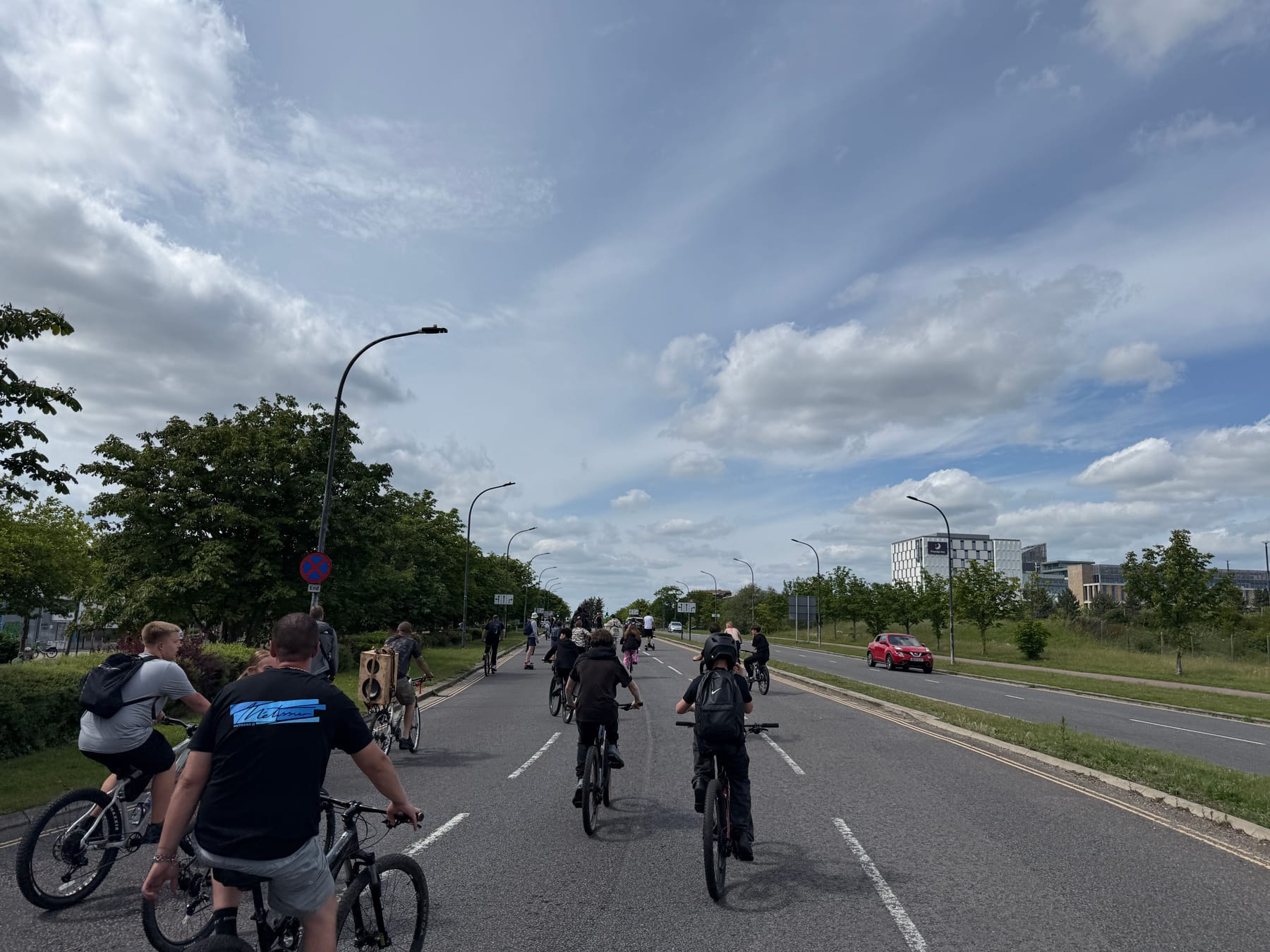
I didn't realize it at the time but I was just ahead of Dom. I spent a lot of the event weaving from back to front and back again to experience a little of everything.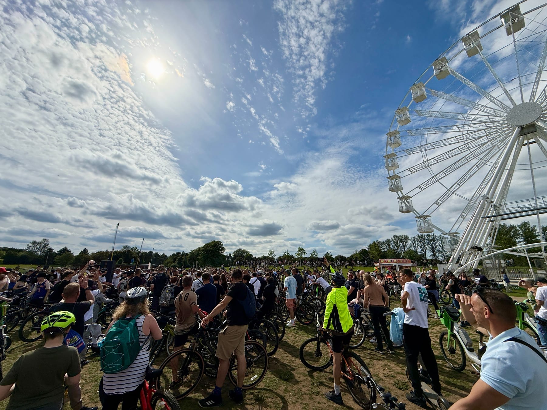
Last stop was Willen Lake. Really good spot to end it with heaps of space for everyone to pile in.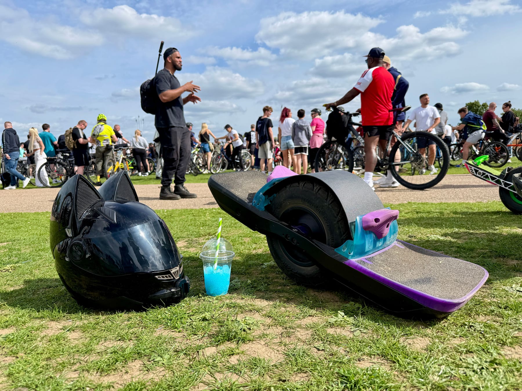
If you want to watch the whole thing from Dom's perspective here's the whole ride. Bonus points if you spot me or other Onewheelers appear throughout.
I hear the next UK one is in Nottingham sometime so I defo plan to go to that too.
-
RE: Onewheel Photoshoot Threadposted in Wall of Stoke
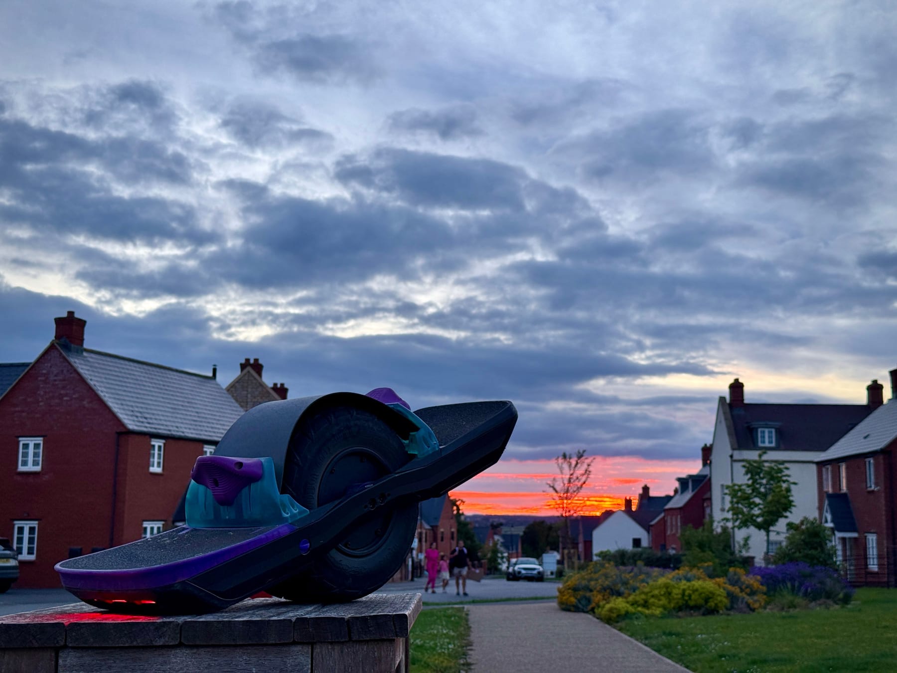
Summer is the best season. Without question 🥰