2 weeks ago me and a few friends attended a group ride unlike any other.
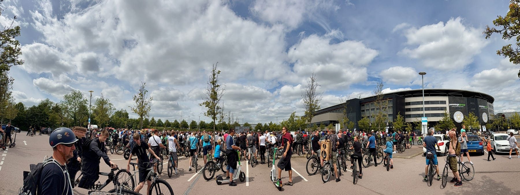
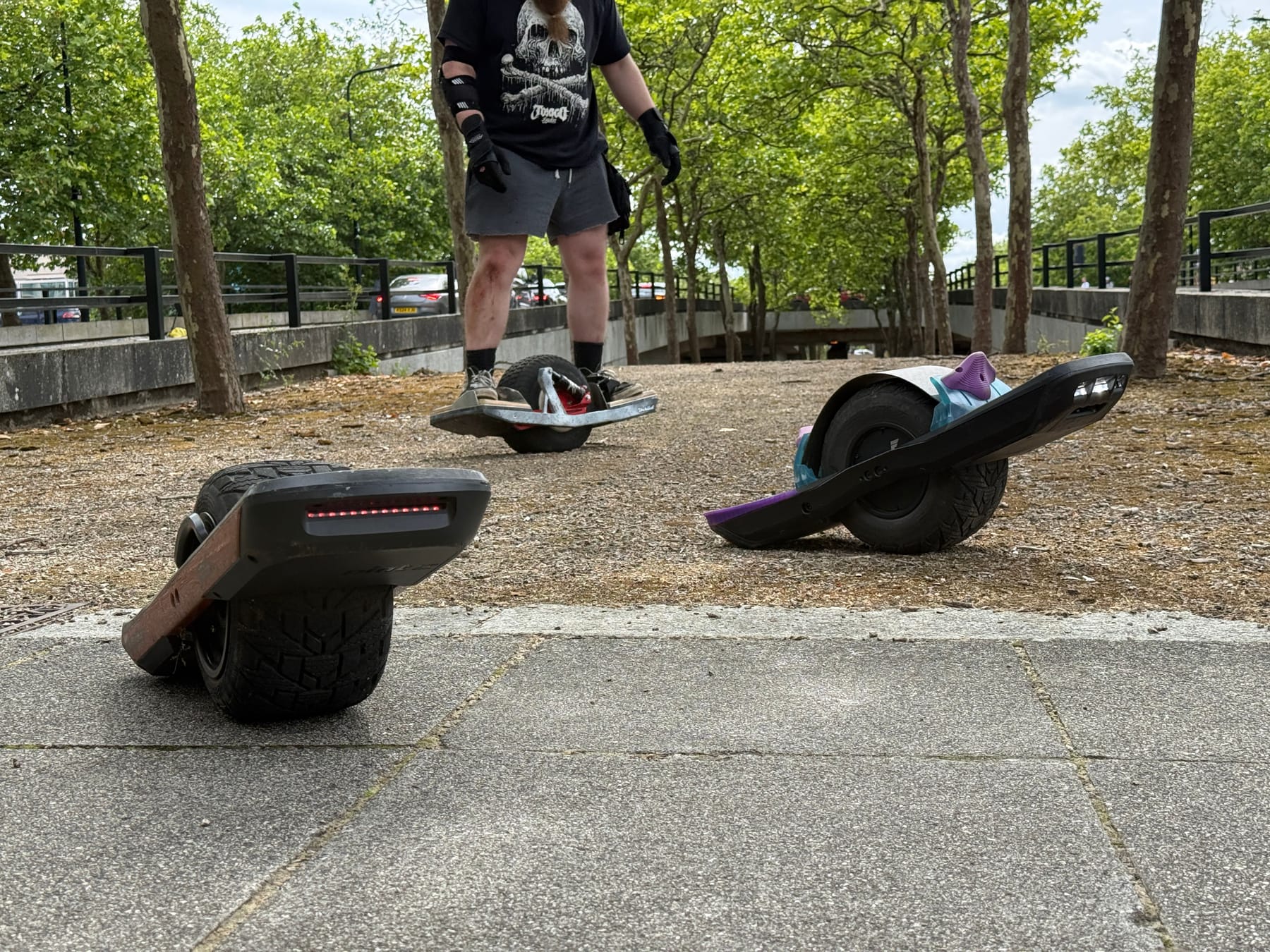
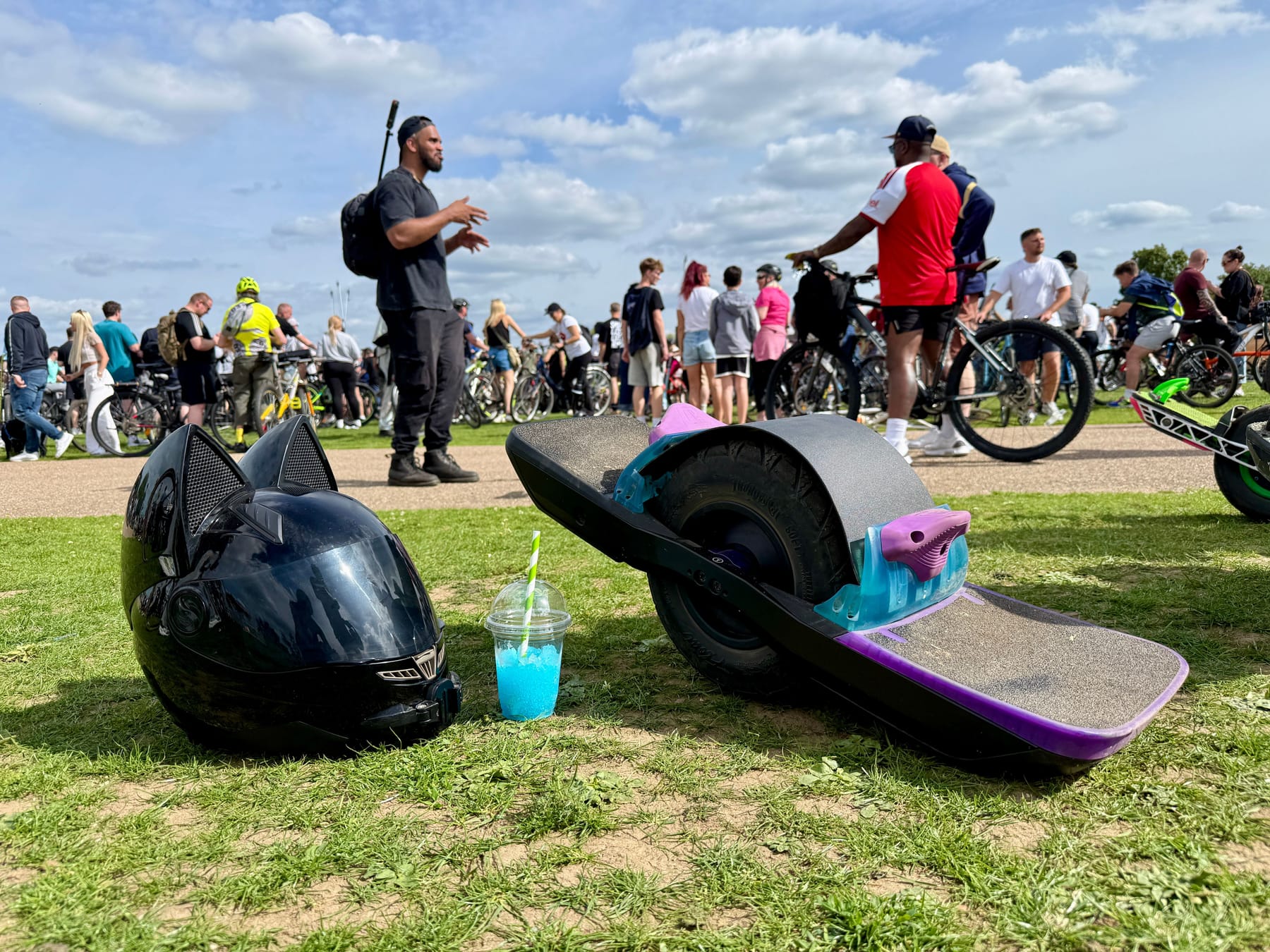
Yes mostly bikes but we had a few onewheelers come to represent.
I think I counted at least 10 Onewheels but there were so many of us DnB heads I can't say for certain.
All I know is we shut down MK that day!
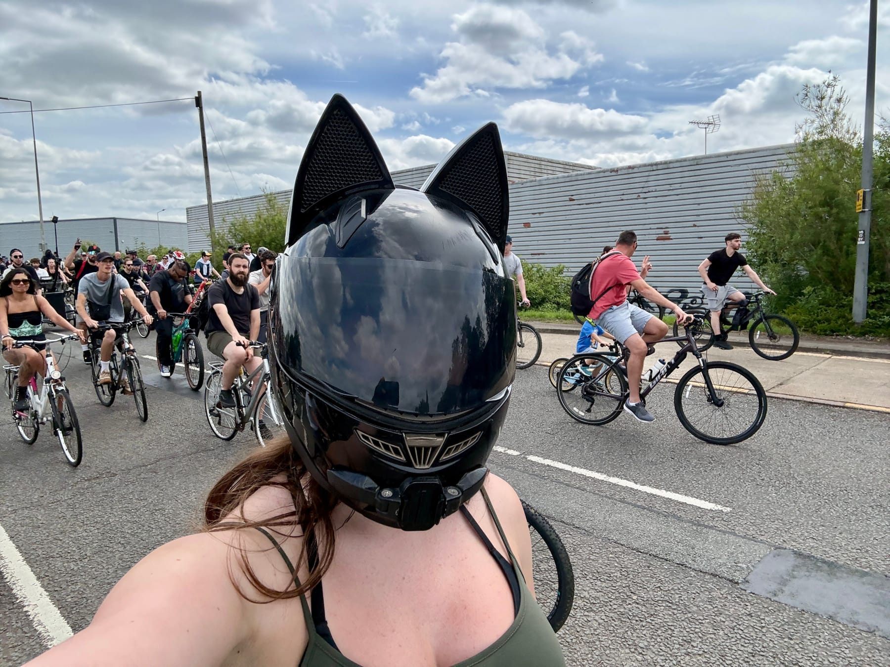
I decided to get up front for the first bit and get some space to carve. Back in the main pack was very closely packed and a little hard to navigate with all the handlebars poking me in the front and regular bottom 🍑
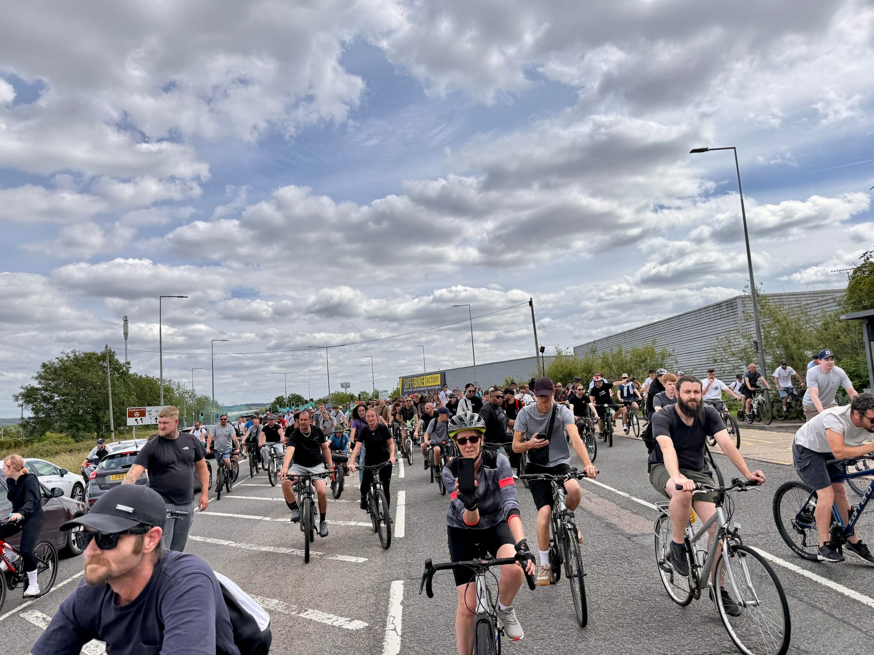
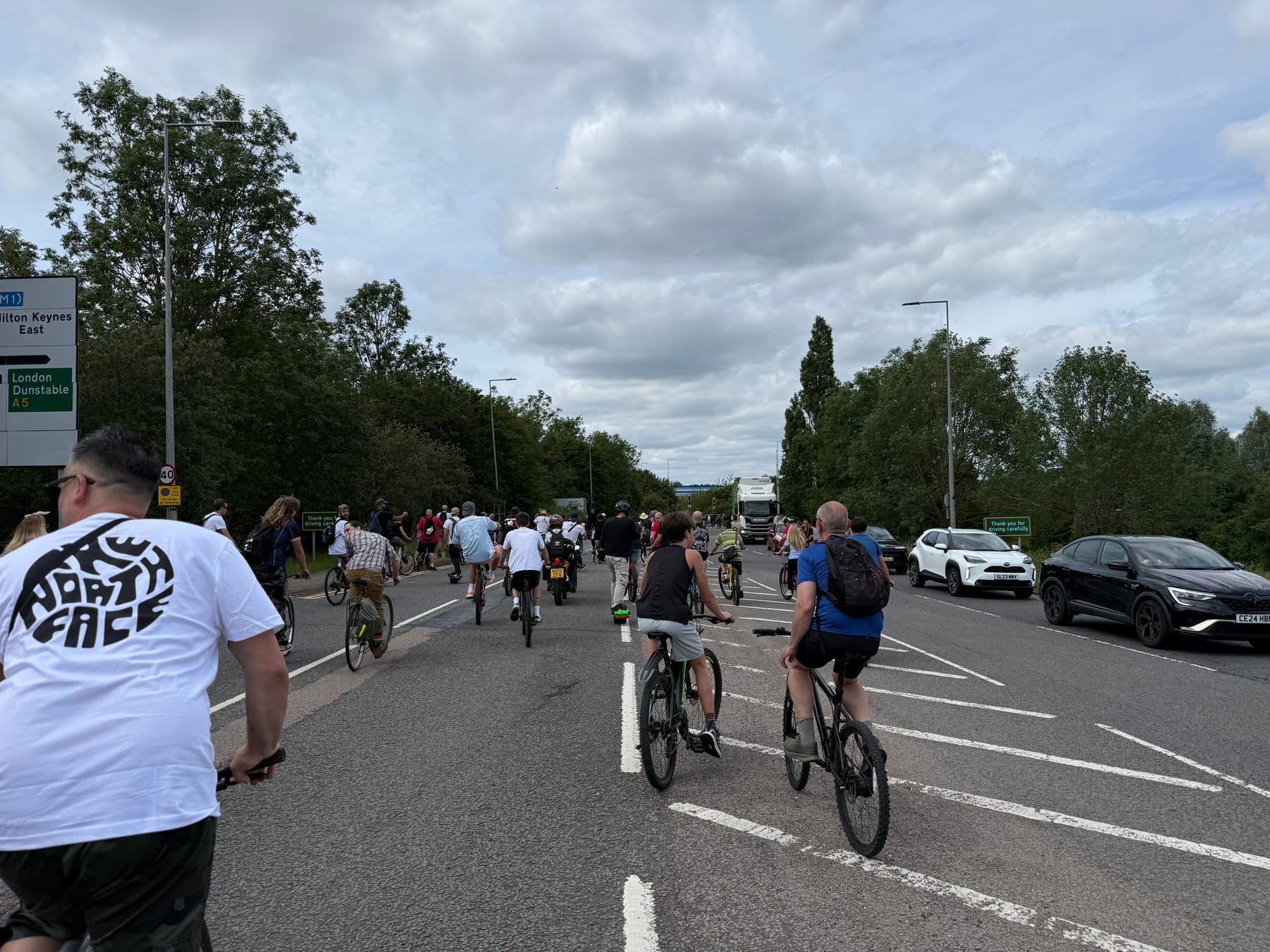
It looks mental now but things only got more insane as we rode as a huge pack adding to our numbers the further we went.
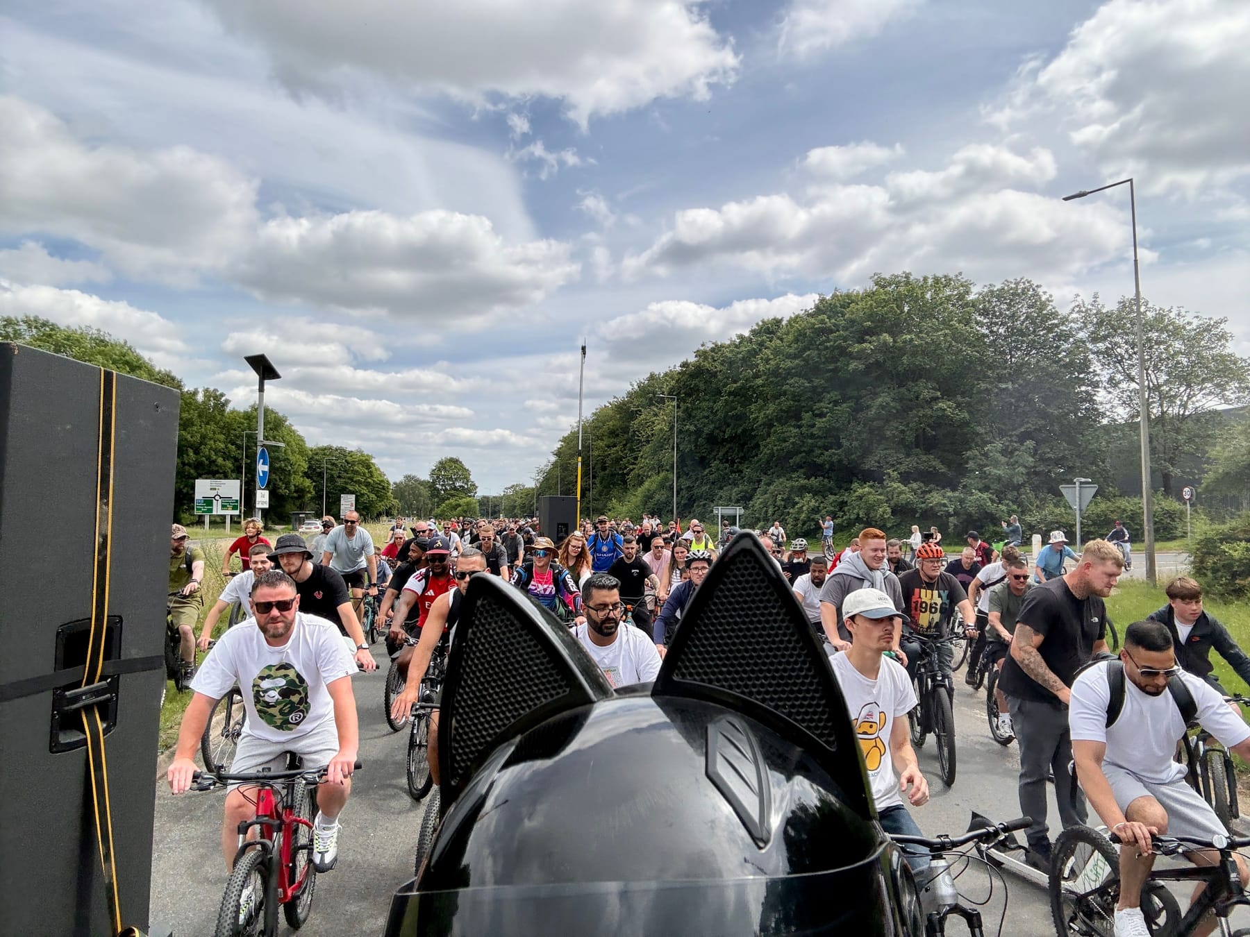
Getting in around the speaker bikes was where you wanted to be. Getting a full body dose of bass. Literally making my entire body shake at points!
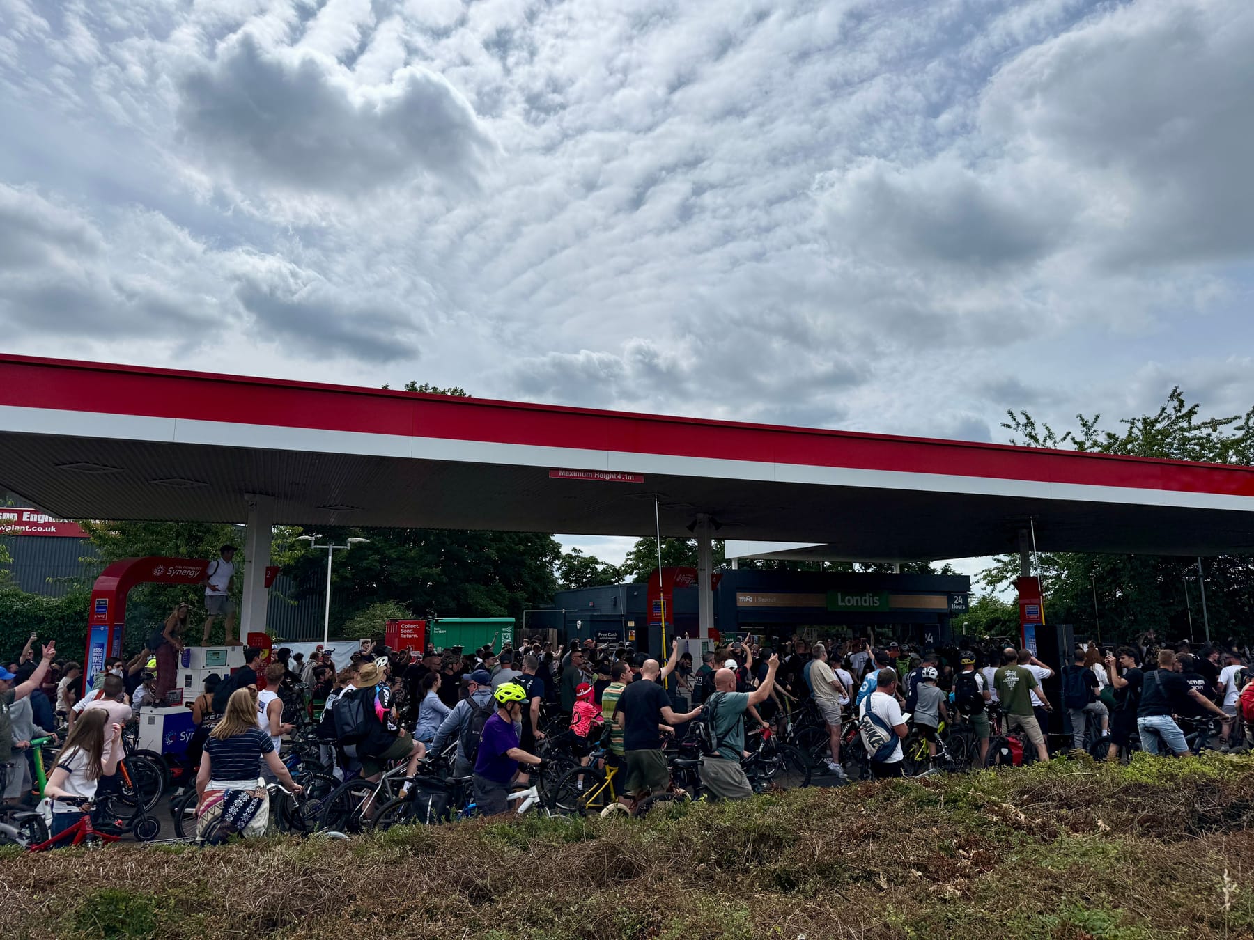
Then we got to the petrol station. Apparently this was the main attraction last year and this year did not disappoint.
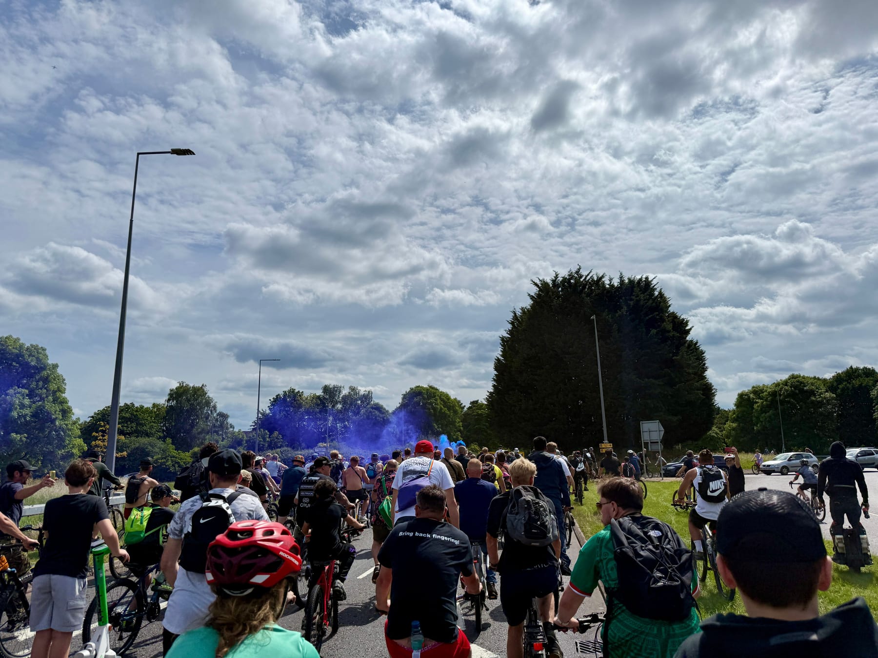
@Beardonaboard just cruuuuising through the crowds outside MK Central Station.
And then helping out a skater get some speed up the hills. With his board being an absolute tank he had no issues towing.
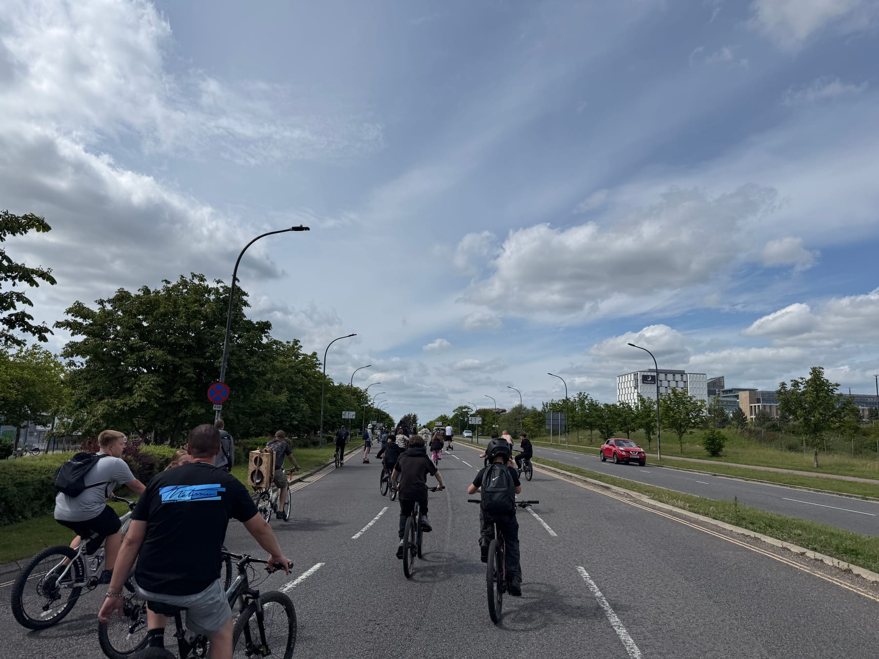
Midride me and gang got to shoot off ahead to get a little break from the crowds.
I didn't realize it at the time but I was just ahead of Dom. I spent a lot of the event weaving from back to front and back again to experience a little of everything.
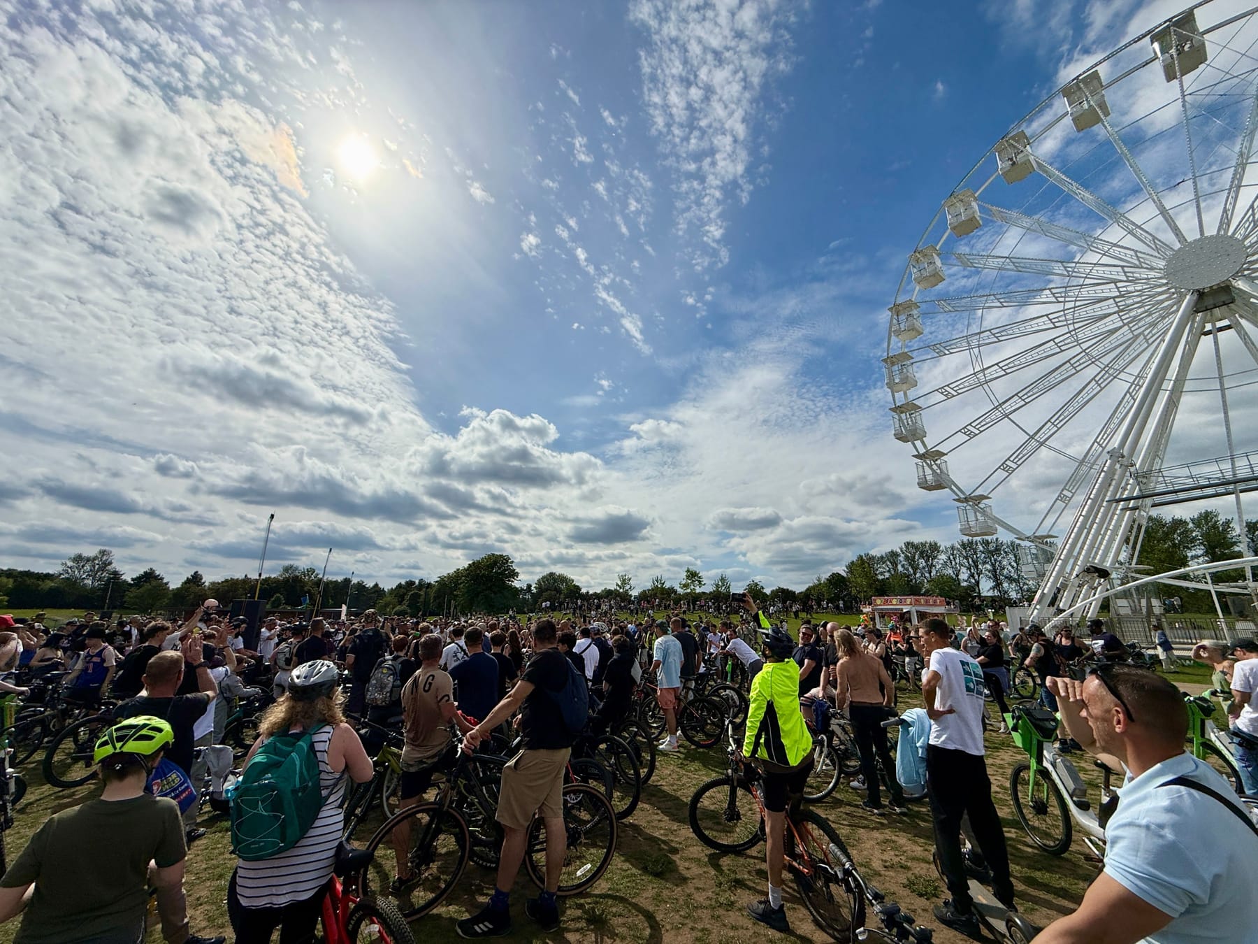
Last stop was Willen Lake. Really good spot to end it with heaps of space for everyone to pile in.
If you want to watch the whole thing from Dom's perspective here's the whole ride. Bonus points if you spot me or other Onewheelers appear throughout.
I hear the next UK one is in Nottingham sometime so I defo plan to go to that too.