Custom headlight and taillight (VESC)
-
@s-leon Thank you <3 The box is a premade one for necklaces but the innards and decor will be all me :)
They're sadly not drop in replacements for the XR but rather designed for modded boards that can interface with an RGB signal (RGBW in my case)
-
most excellent @Lia!
-
@lia That's pretty cool! Can't wait to see them out in the wild!
-
Well look what decided to show up. So many LEDs 0.o
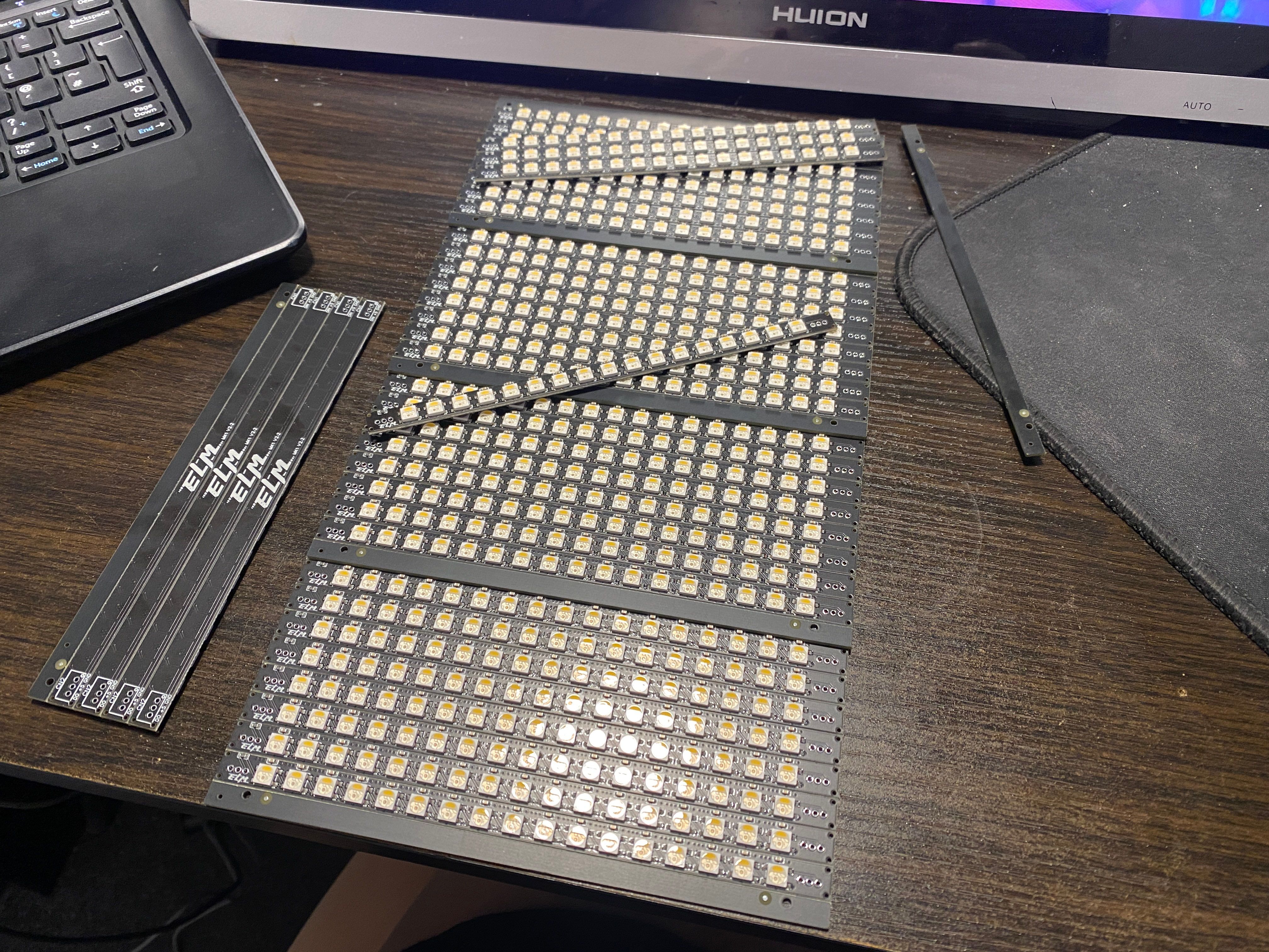
Work is busy today though and I'm the only one covering support so haven't been able to take pics of the test I did but they work!
Going to make a jig to separate and test these all then see how they compare to the XR, Pint and even my initial version.
Update post to follow in a few hours x
-
-
I spent way too long trying to validate this and my eyes are on fire. I can still see multiples of 17 dots across my vision and a headache to go with lol 😖
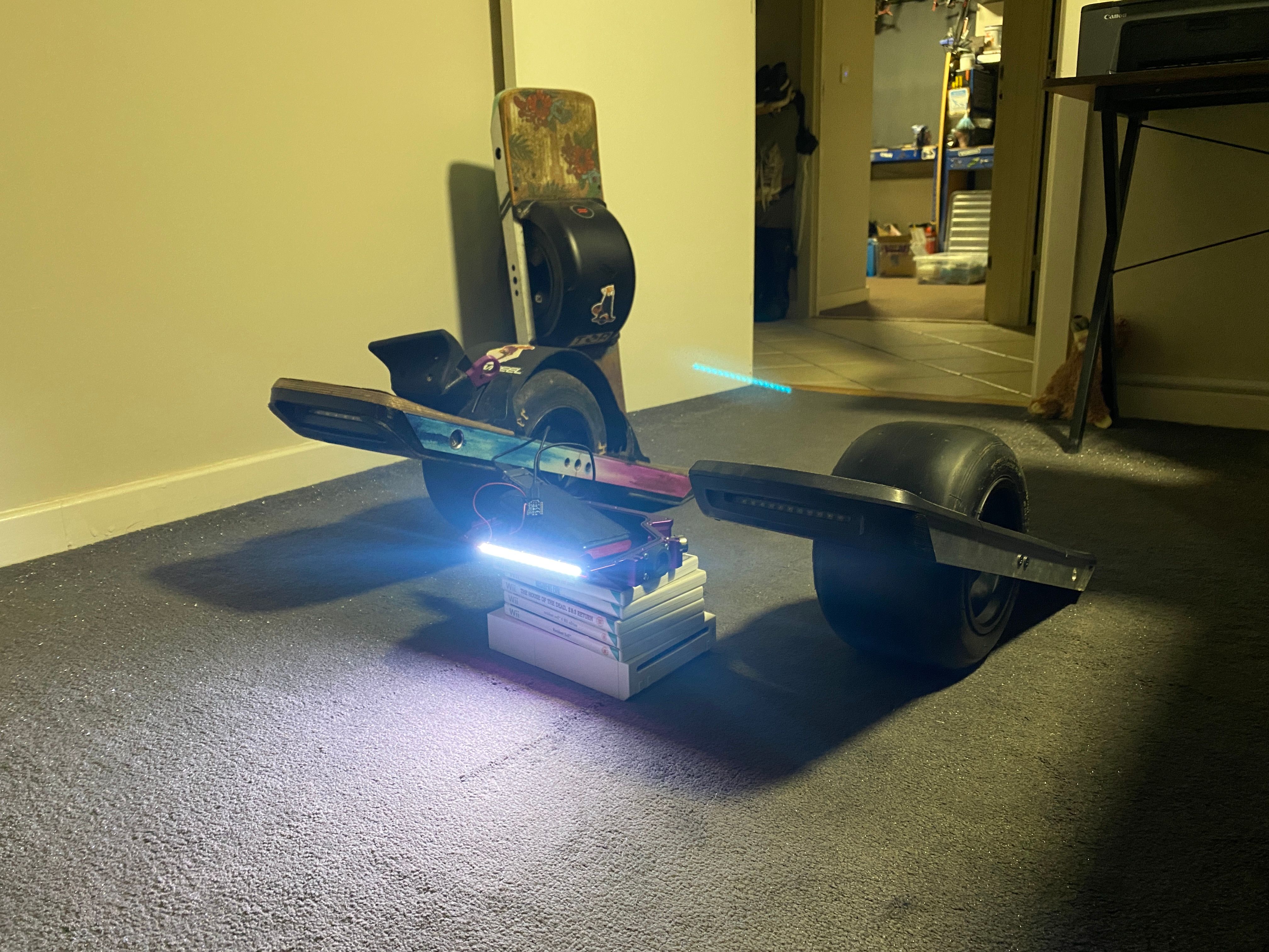
Testing is done (I hope) and it looks like it's keeping up just fine with the XR. Hard to get on camera but I gave it my best with my iPhone on a tripod so it didn't move too much.
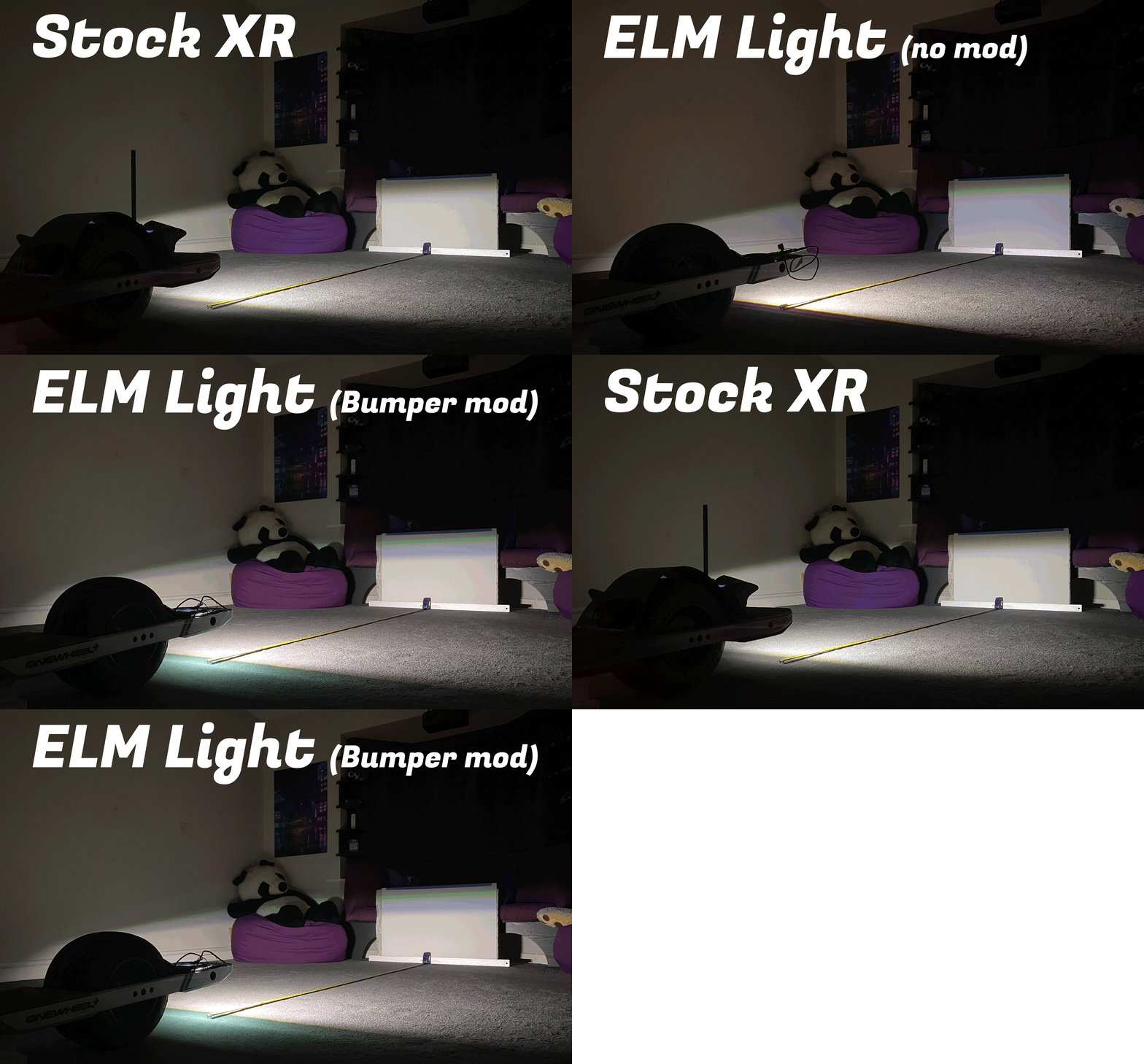
For each test I had an A1 sheet of foamboard 2.5m away from the boards in each since that's as much room I had to work with and felt like a good way to validate the brightness :)Also did the Pint but it wasn't worth adding in the above gif.
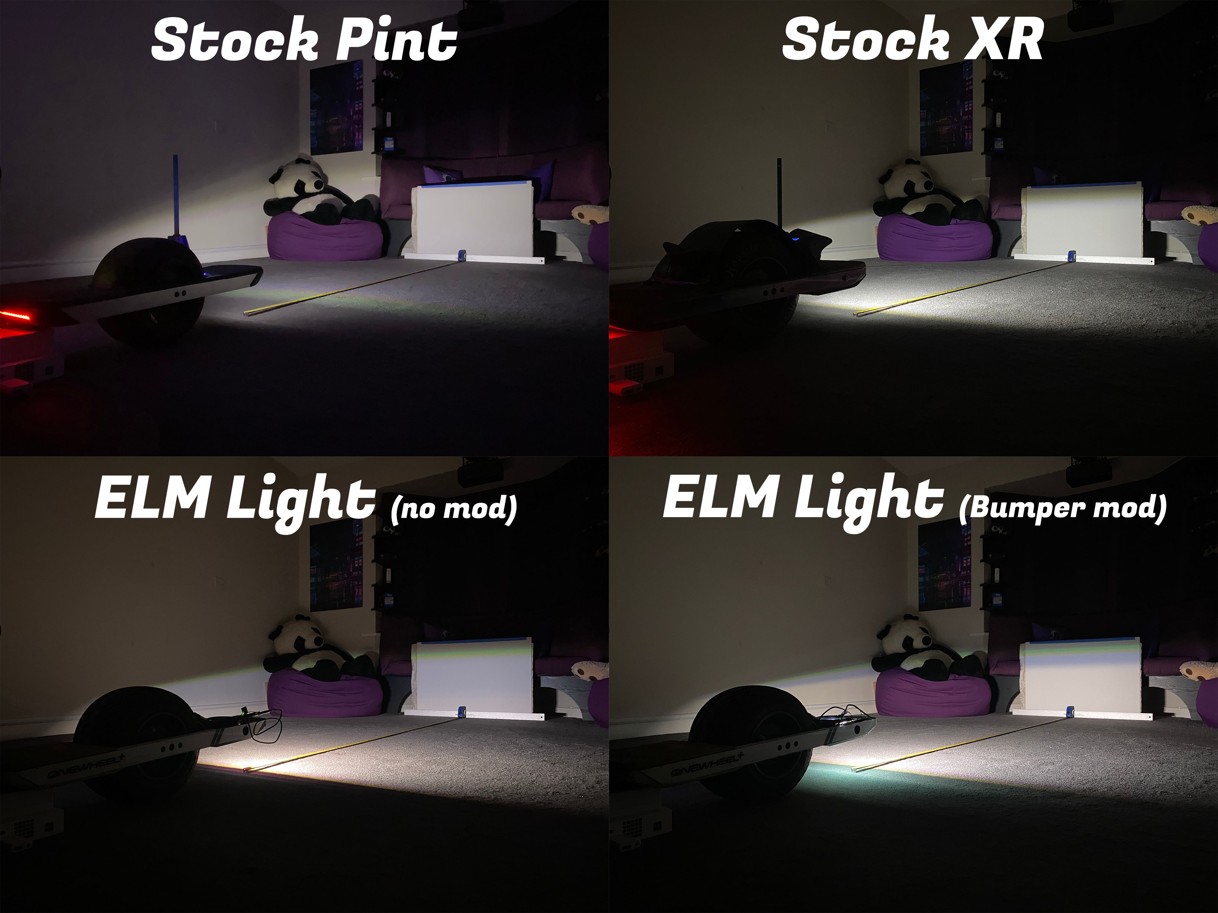
(Yes the Wii and games are certified scientific testing apparatus)So what's with this "Bumper Mod" mentioned in the images I hear you ask (I'm in your walls). As it turns out the stock bumpers have a tiny window that was blocking some of the LEDs seen below.
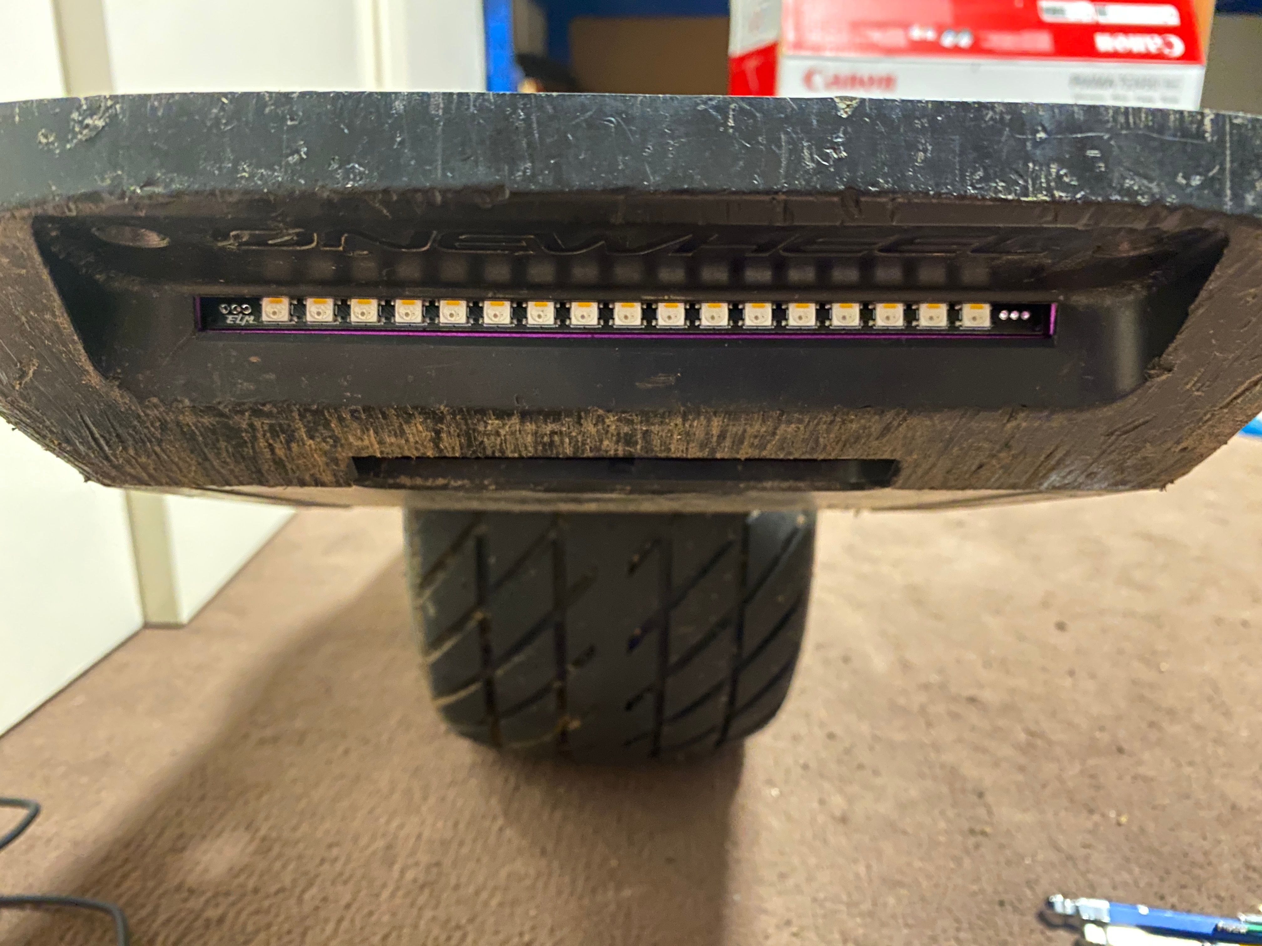
The dedicated white segments of the LEDs were obscured so although they shone nicely below it didn't do much up front. However there is a bit of overhanging plastic you can easilly remove with a file where you get the below results.
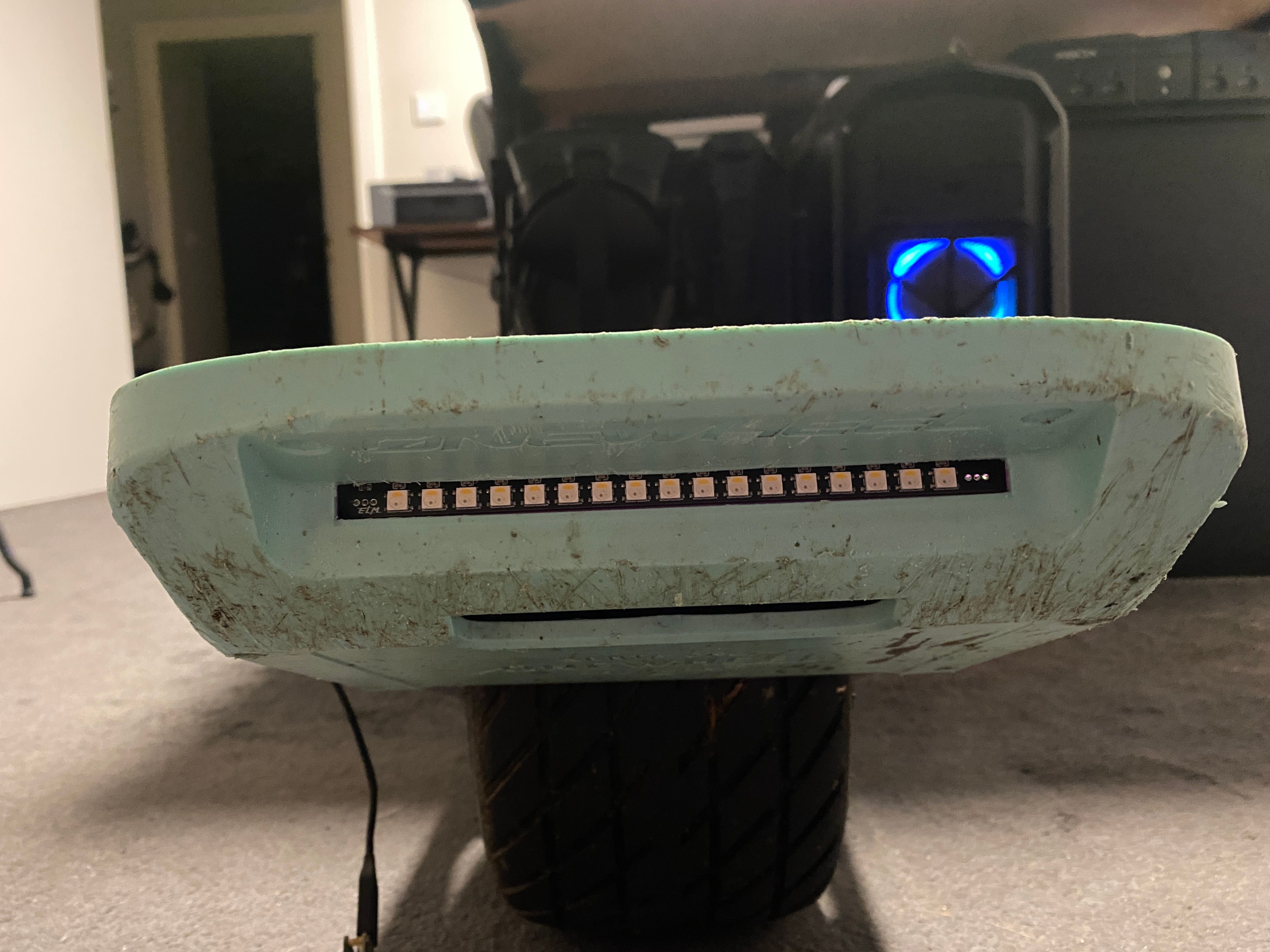
The mod as you can see makes a slight difference in how much extra light makes it forward rather than just down where you get a clearer cutoff line for where the white channel reaches.
V2.3 Might have the LEDs rotated 180 if I can pull that off without completely changing the layout of everything else however I'd doubtful it'll make that much of a difference so either version should be fine.
Guess I need to finish the packaging then and sort out how I'm going to sell the first batch off.
Stats in case you wanted.
Full white (That's RGB set to 255 and the White channel too) draws 0.72A per bar @ 5V
Full red (That's Just the red channel at 255 and nothing else) draws 0.16A per bar @ 5VSo in theory you have 2 with opposing white/red total current draw is 0.88A @ 5V per bar or 4.4Watts to run a pair in a "normal" config.
-
Okay I had too...
If you have RGB you have to have it shoot rainbows.
Also added a demo turn signal animation as a proof of concept.
You could probably get way more creative with it and make it more clear. On cam it just blows out the sensor so not easy to record it but you get the idea. -
@lia thank you for creating this and doing these tests! It’s great to see it working so well.
-
@batterymooch It's been a lot of fun :) Learning how to do full production CAD in EasyEDA and get a PCB fab to make these was new.
Thanks for swinging by <3
-
@lia
I must buy these. They look fantastic.In your testing, what are you using to drive and/or control these?
Cheers!
-
@theboardgarage I’ll be sure to keep a set reserved for you on the first batch :)
For testing I’m just feeding a data signal using a seeeduino (tiny little Arduino the XS will be using) using the neopixel library. Really simple to test with and I hear the VESCs support RGB and RGBW now so this should just drop in with a decent buck converter to supply the 5v.
-
This post is deleted! -
Packaging being made. Nearly ready to put up orders for the first batch :3
Hopefully this weekend with @cheppy44 's help.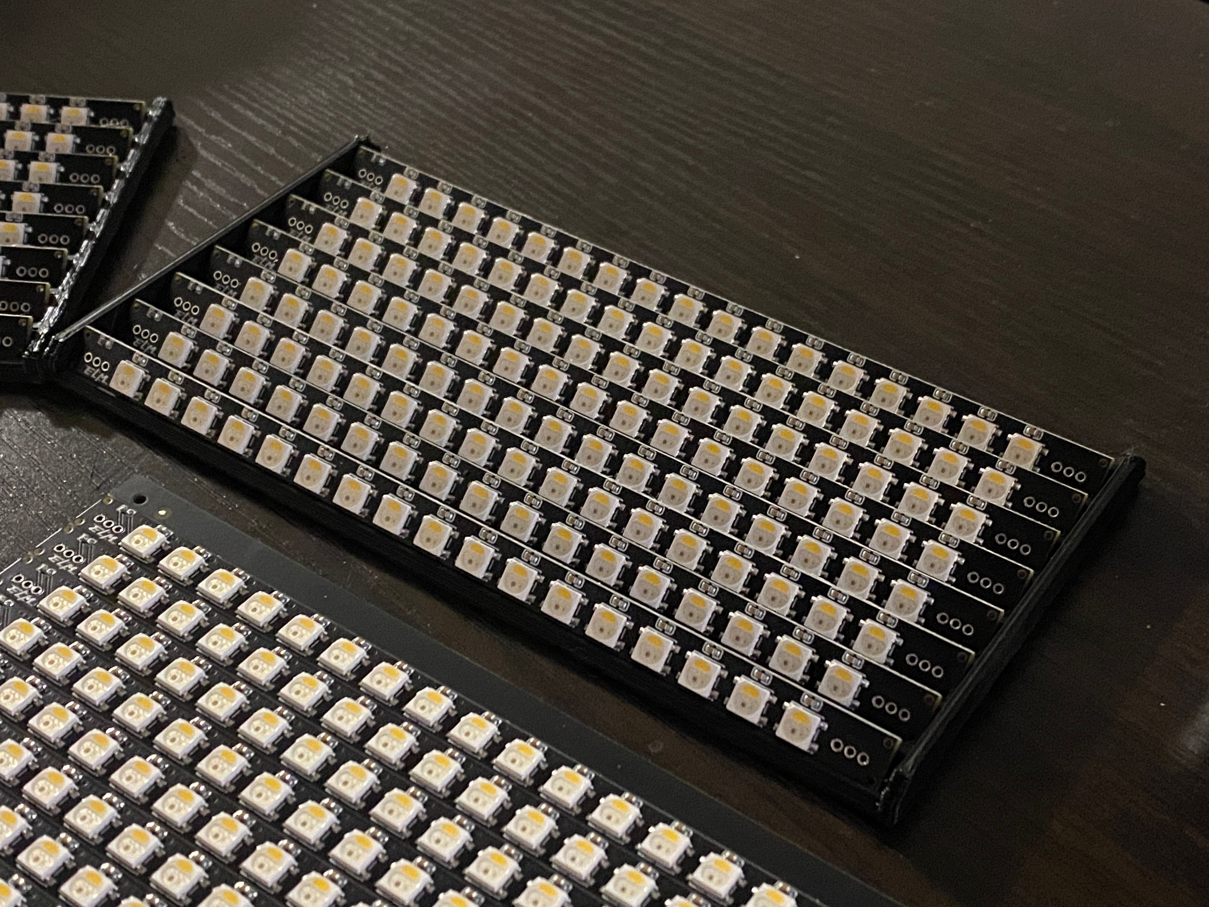
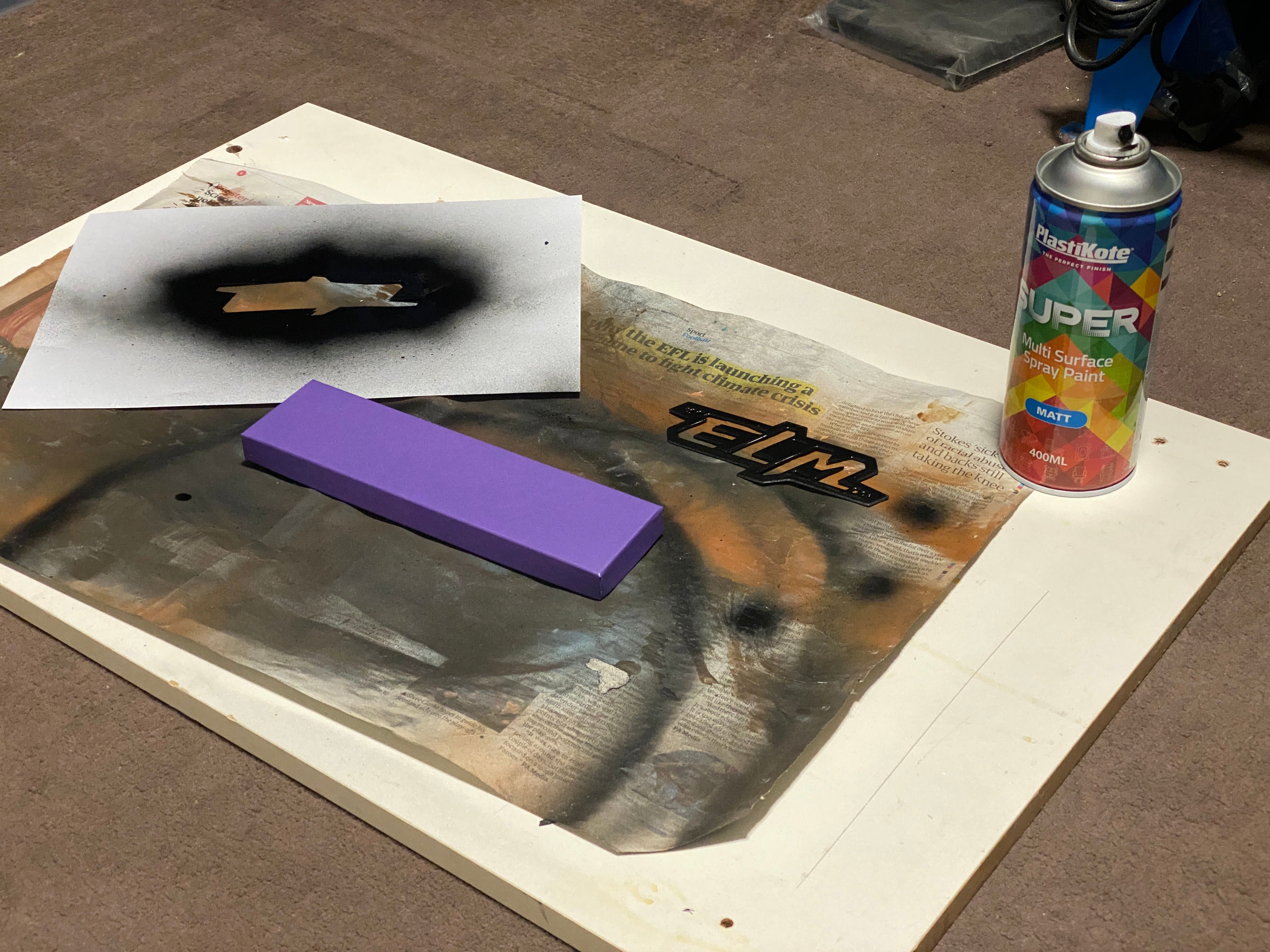
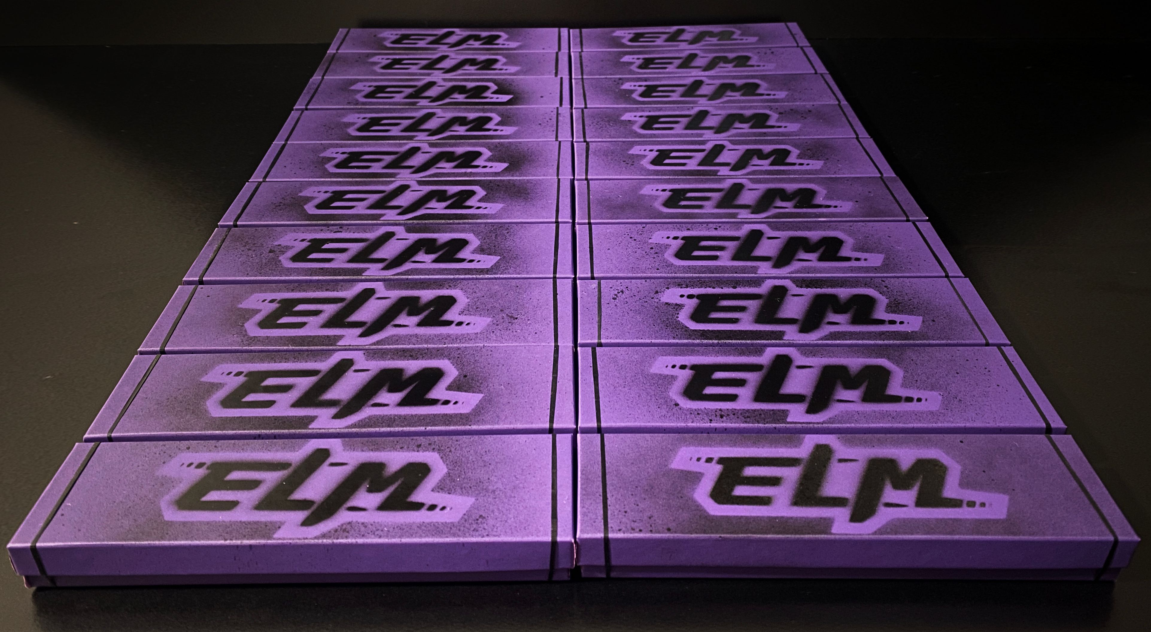
Each box gets a bit of my shoddy spray painting (It's artistically bad I promise)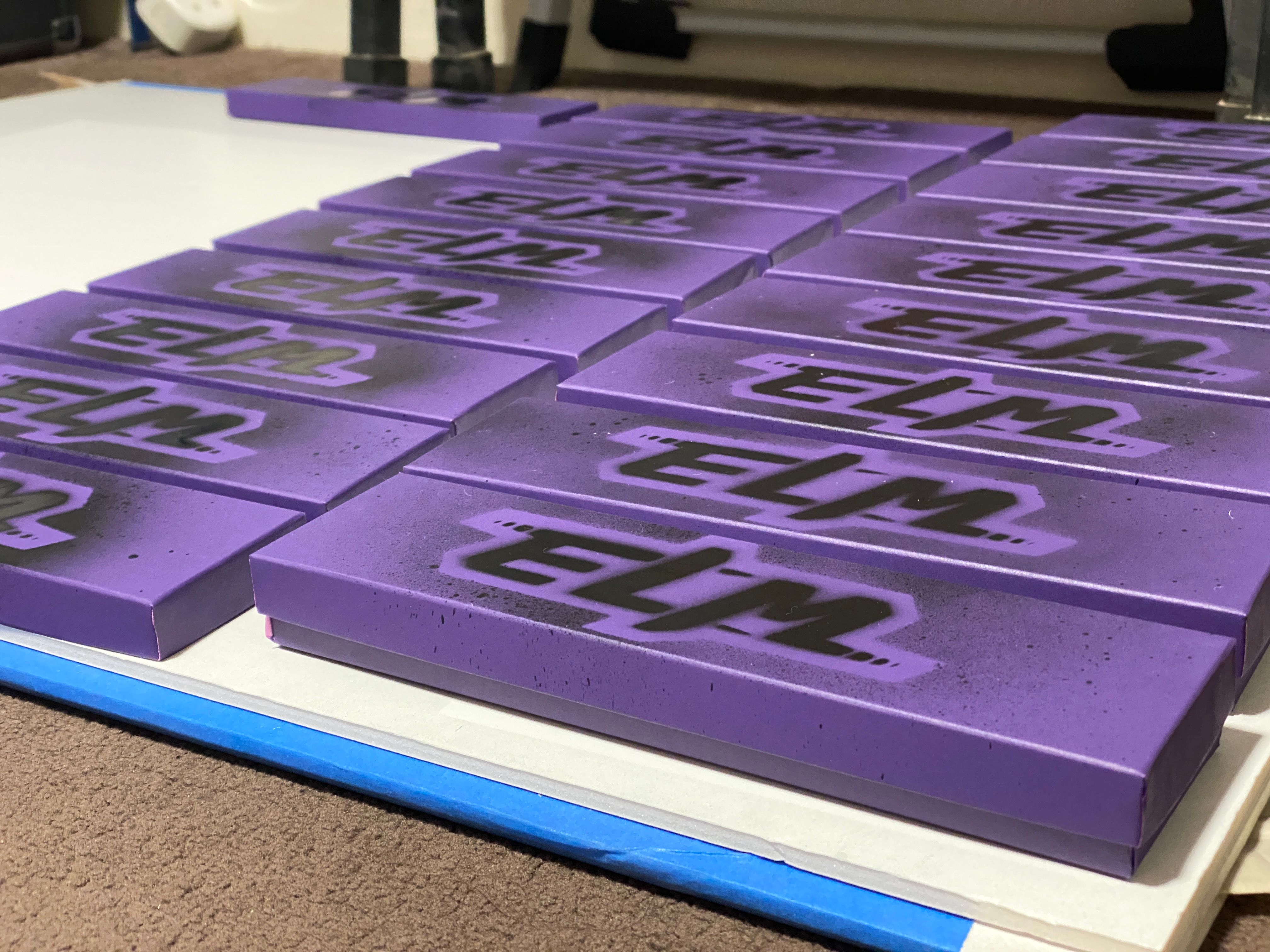
The rest of the boxes waiting to dry :3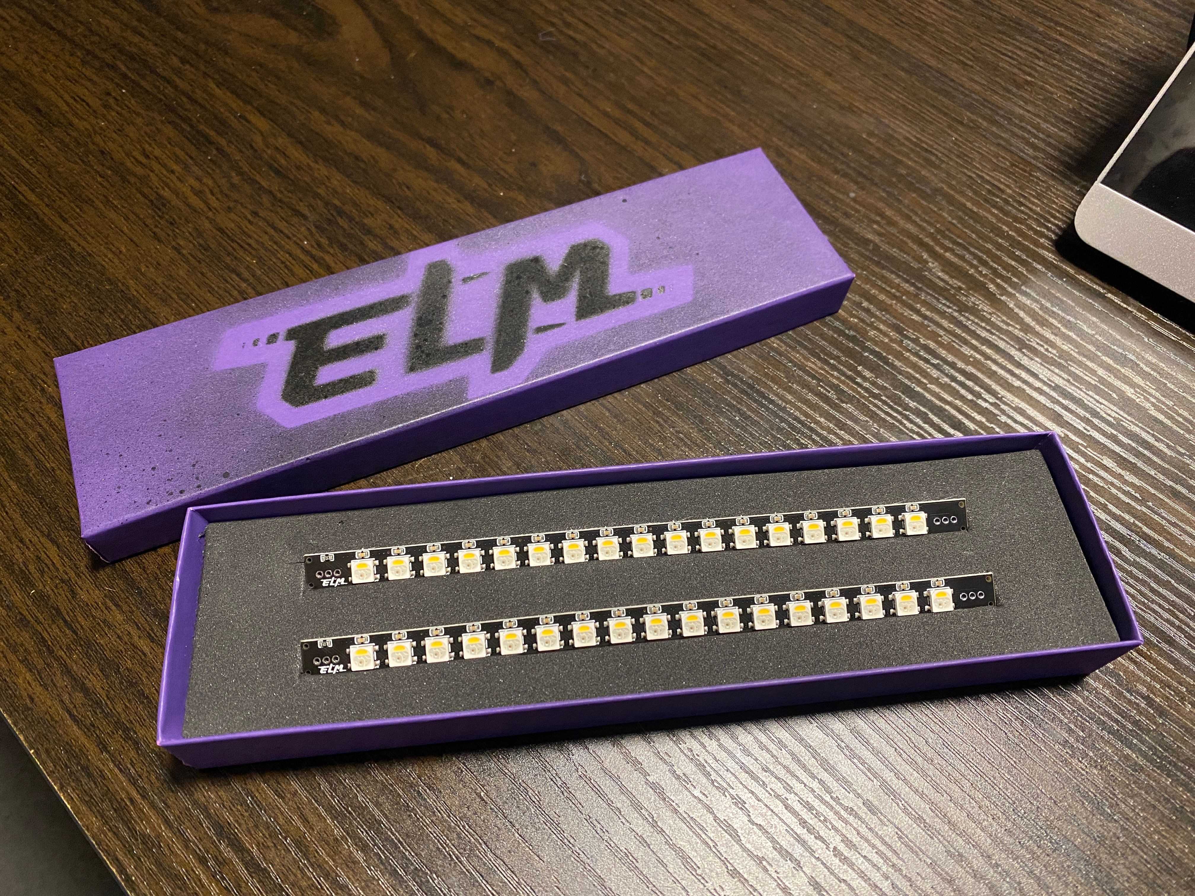
Test of the foam inserts and fitment. I think it looks nice and doesn't come loose no matter how much I shake it.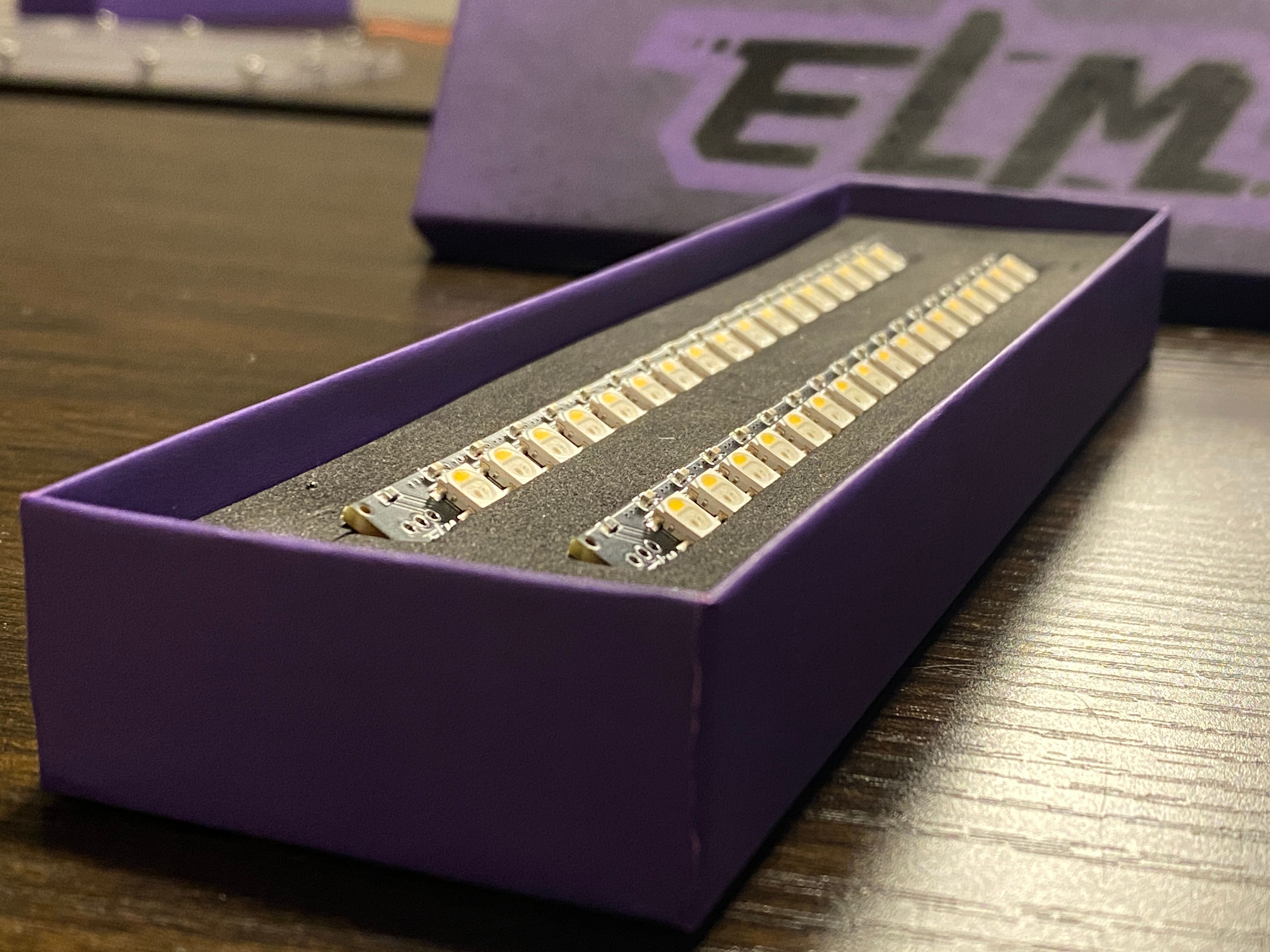
There's only a few on the first batch because I have no idea what sort of demand there are for these but I've already ordered 2000 LEDs for another few batches just in case with an altered LED orientation.
Back to work I guess <3
Follow-up post with better pics, included bits and whatever else I'm forgetting. -
@lia said in ELM custom headlight and taillight (VESC):
Each box gets a bit of my shoddy spray painting (It's artistically bad I promise)
The overspray look of the ELM logo is incredible!
-
@hanahsdax I really like how that turned out too, it's crazy messy but worth it :)
-
Looks excellent. I look forward to these.
-
@theboardgarage Thankies <3
I'm sure you'll love them :) I can't wait to see what people do with these with whatever special sauce is being added to the VESC firmware.
Nick tells me you're after a few more so we'll set aside a bunch from the next batch for you too. Still have 1 from this batch reserved as well x
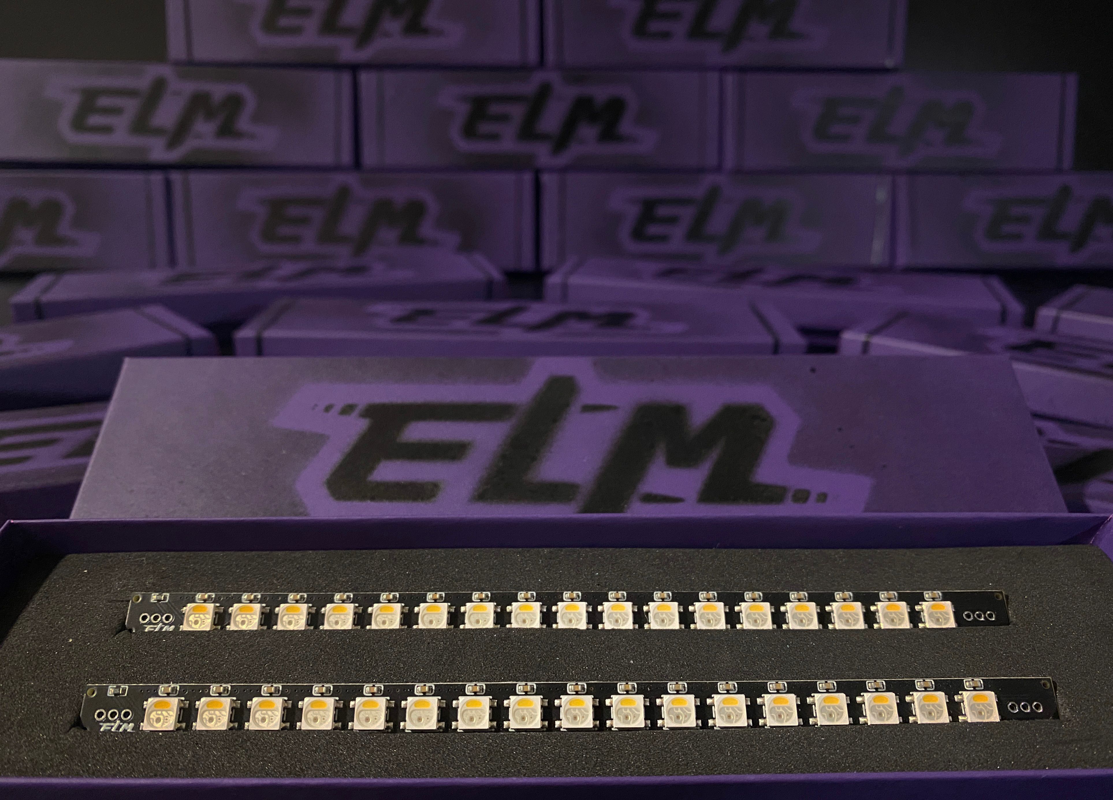
We're going to allow orders on Saturday Noon (Central Time) in Discord.
Once the first batch are gone (there's like 11 left) we'll be doing a wait-list as I'm currently waiting for the delivery of the LEDs to begin the next batch which I'm ordering WAY more of this time.
-
All of the headlights have shipped and a handful have theirs already (no thanks to customs delaying a bunch).
I haven't made v2.3 yet as I wanted to get some feedback on the initial v2.2 version and so far some things have came to light.
Nick has noticed while testing with a modified VESC (using the servo port as an RGB led driver) is the voltage levels on the data pin aren't enough to trigger the high and low thresholds for the LEDs. Even after some research I'm unsure of the specifics but Nick did manage to get it to work with a simple logic shifter. I had this working on Seeeduino (Arduino) and ESP32 so although 3.3v logic can drive this it doesn't look like the servo port has the ability to do so natively. It's early testing though so those working on that mod might come up with something.
Logic shifters usually require the low level and high level rails supplied along with GND and the data in which would be one more pin than I am able to fit on a stock ELM box due to the extremely restrictive size of the passthrough holes that were added.
As such I'm looking at making a logic shifter cable to link the headlight and VESC if used as an optional extra. This would mean it makes sense for me to add a connector to the headlight which would then in turn mean minor modification to an ELM box if anyone chooses to use it with one. A file would be needed to make the passthrough hole slightly taller and wider for this.
I plan on using a JST-PH connector which are spec'd for 2amps so that it has plenty of headroom when used to provide power to the LED and also something else on the other end if used as a passthrough.
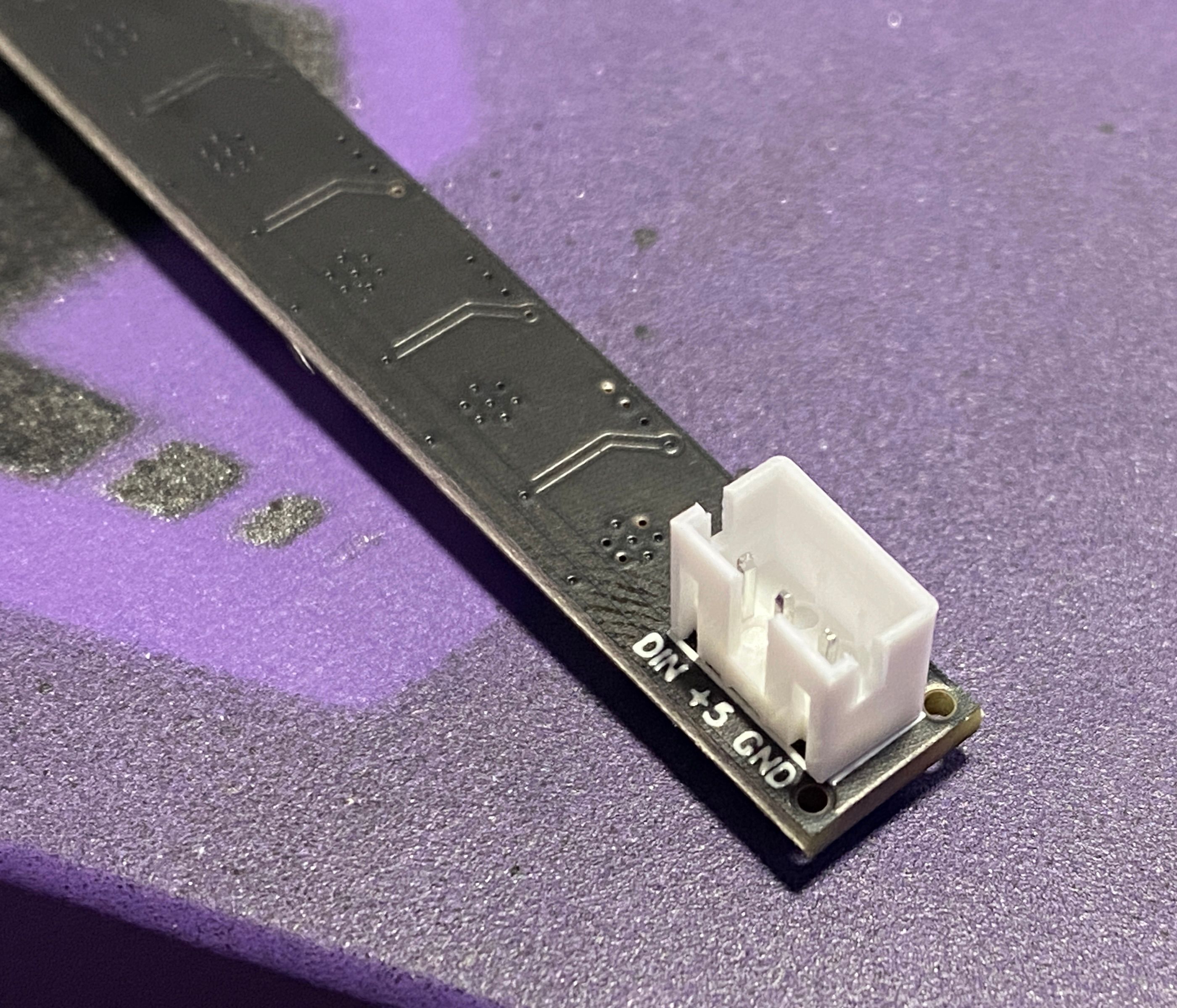
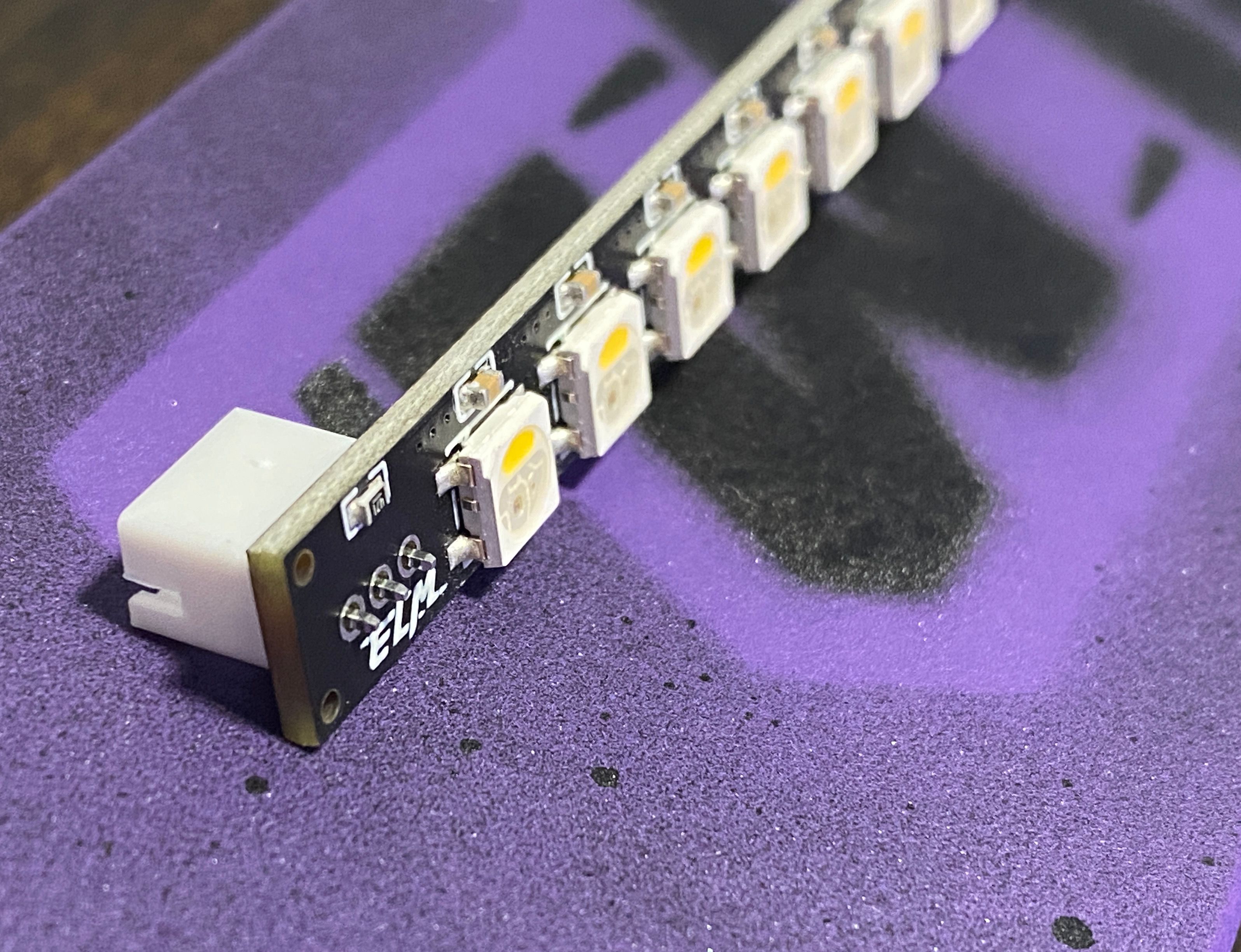
(I haven't soldered it I know, it's a dry fit)
Smaller connectors are only 1 amp which would mean it would be easy for someone to overload it carelessly. I might be a complete novice but I try to not put low current connectors on medium-high current draw things ;)
On a completely separate note the next version of these headlights will likely not be branded with ELM as the guys are doing their own thing and it doesn't make sense to use the logo anymore. I'm working on another name and logo to put on these with Nick, possibly to go with the GT-VESC ecosystem too but we'll see. Until we've settled I won't amend the thread to avoid confusion. We have one thing already and a 'finished' logo but I'm unsure yet if I 100% like it.
-
Looks great! When I vesc my OW later on down the road, I might pick one of these up for myself :3
-
@loaffette Thank you :)
Hoppe your future VESC goes well :) I'm hoping to make a new board rather than convert one of my current ones. I'm kinda still loyal to my stock boards lol.
