Followup to the Onewheel XS
-
@lia Had some catching up to do here. Omg im speechless!
-
@maciak Aha lots to catch up on indeed, glad it's fun for everyone else to follow :)
I don't tend to share a lot on Reddit since it's really not built well for documenting stuff like this. Probably due to share it again there soon once I've done the LED driver side.Edit: V9 of the battery housing finished and with some adjustments I can now use the blue wrap on the battery. Looks sooooooo much better now :) Also added some foam to protect the balance leads from pinching when being wrapped.
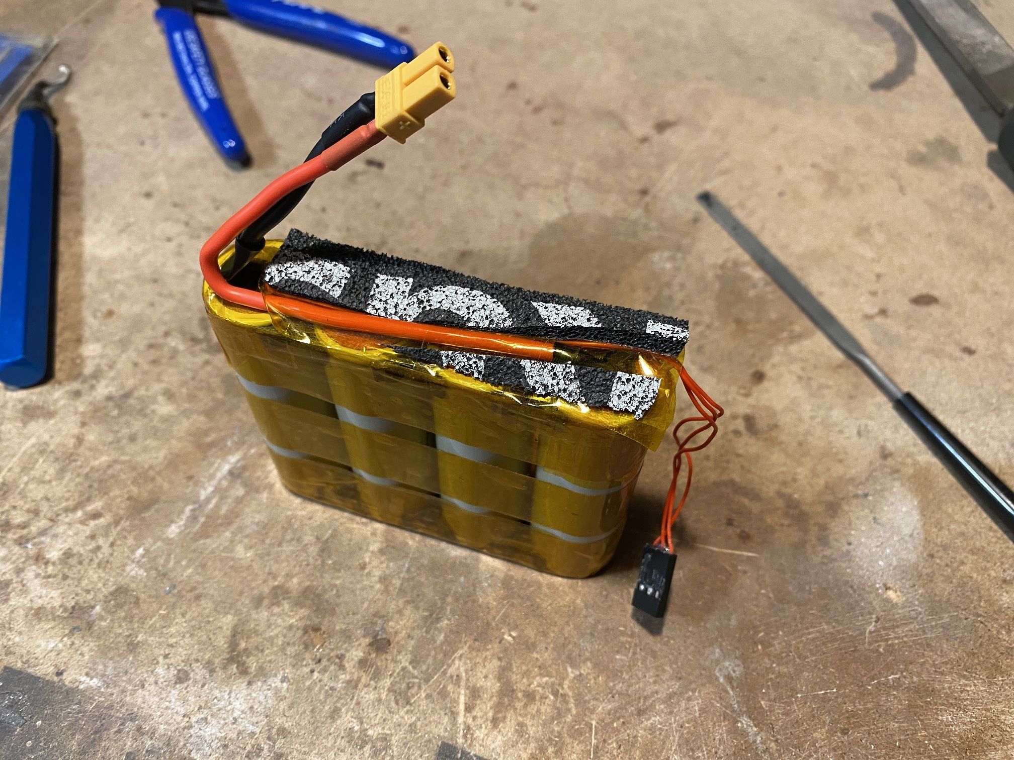
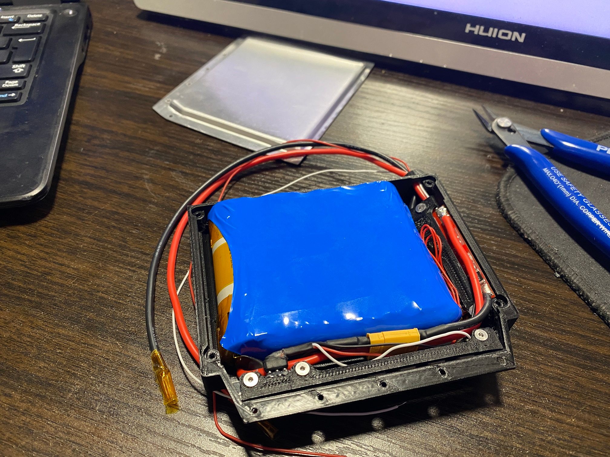
Totally didn't cover the whole pack just like FM does to stay true to their design and not because I didn't want to redo it >.> -
It was going so well.
Intercepting the output of Pin3 on the BMS doesn't disable the discharge mosfets and the transistors on the LED driver seem to operate even when the gate isn't active.
I feel like I'm missing something on how transistors like this operate. Almost like the tiny pnp transistors (S9012) I got are reaching some breakdown voltage. As for the BMS... no idea. Even triggering a fault doesn't cut the output completely making me wonder if these tiny cheap BMS's actually work 0.o
Maybe a formal education in electronics would have helped if I could have gotten one >.>
-Dramatic recreation of me googling things for the past few hours while at work.
Edit:
Okay so checklist of stuff I need to figure out still.- Change the LED bars from common ground to common VCC so I can use more commonly used NPN transistors.
- Redo the driver board to use NPN transistors with the throughhole C557B ones I was testing with that I know work.
- Summon all the dark arts to get the BMS to do as I say. That ooooor.... I cheat and find a way to get the 3A button to take 10A.
- Footpad wiring. Still waiting on the FSRs >.>
-
New PNP transistors arrived aaaaaaand same issue. However...
I wired the transistors wrong on the PCB...
*literally screaming*

WHY IS ARE THE PINS NOT LAID OUT LIKE THE CIRCUIT DIAGRAM REEEEEEEEEEE
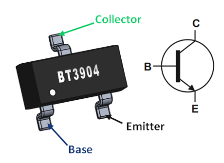
The through-hole components have the middle pin as base so I just assumed the SOT-23 ones would too :(
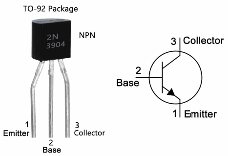
Who... Whom... Whomst did this! Why don't I read spec sheets properly D:
How have I gotten his far and not set fire to something yet.Rotated the little transistor, as tiny as it is I managed to get it in place in the wrong orientation to correct the misalignment and it now works.
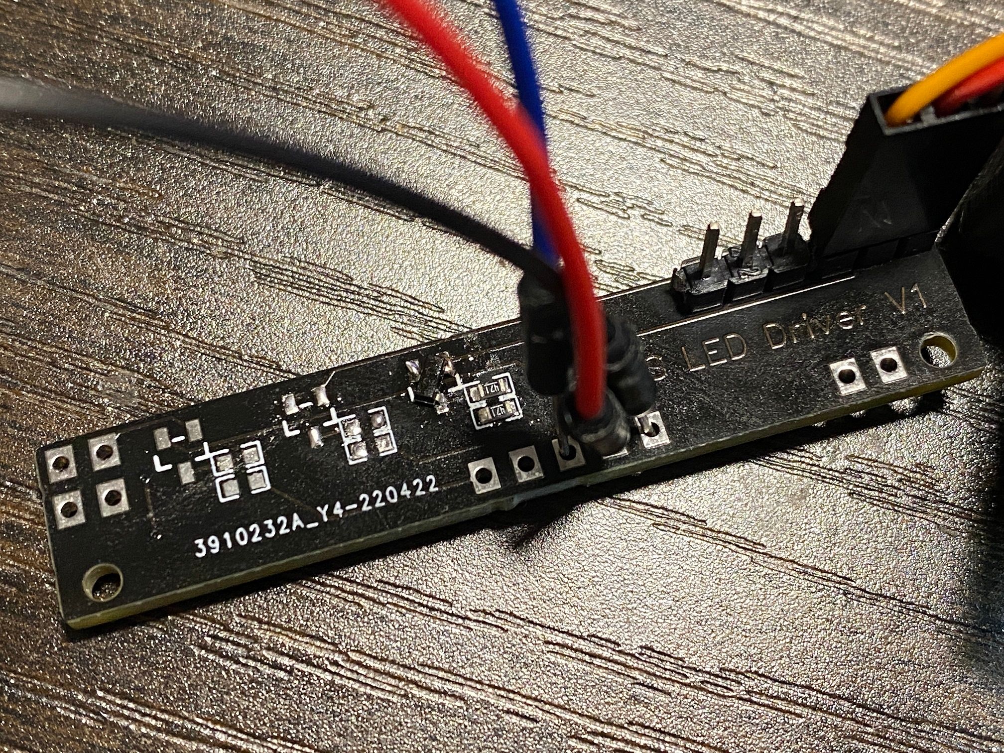
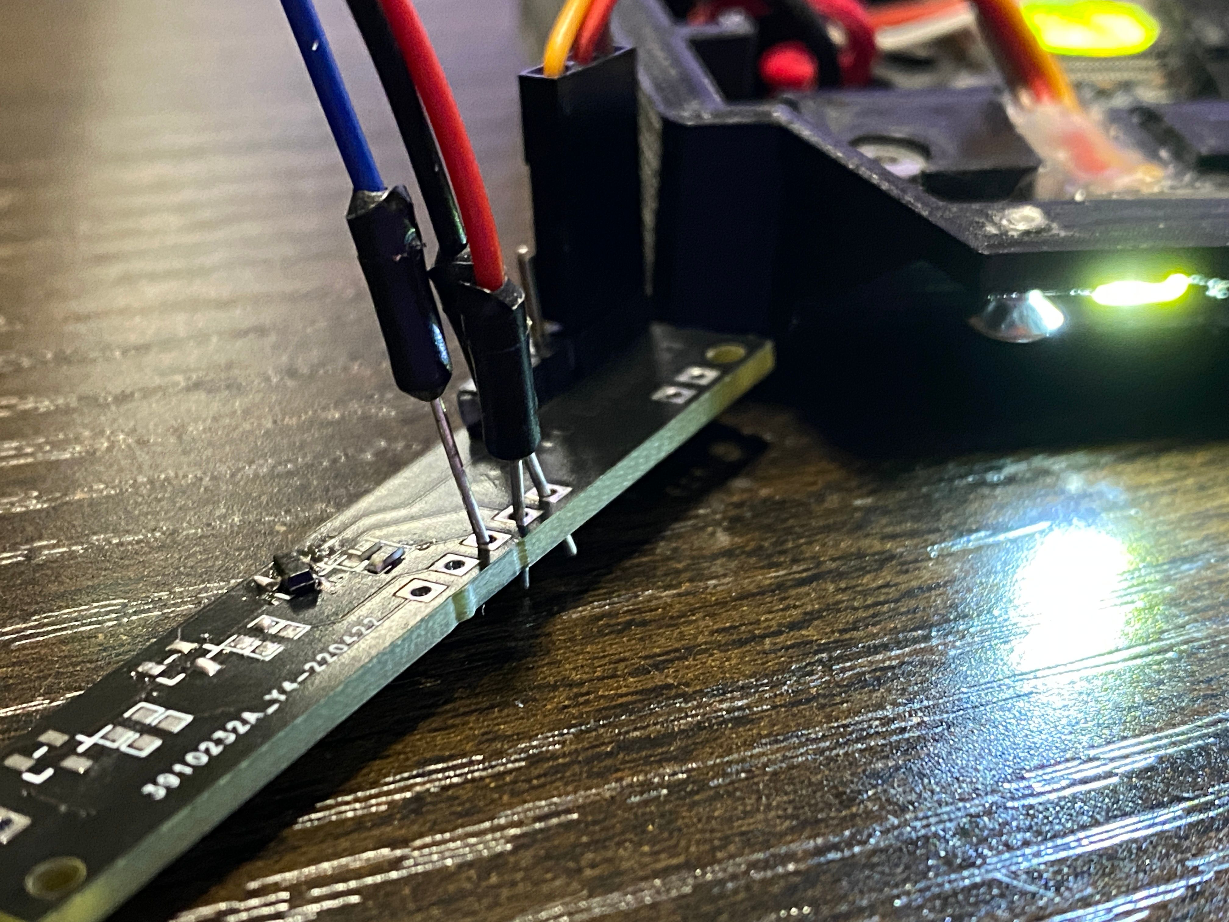
I've done a bunch more but until I have the LED driver in and operating off the internal Arduino Pro Mini instead of my test Arduino Uno I'll hold off sharing the other bits.
Let this be a reminder that I, Lia, am indeed a moron.
-
@lia -- It looks to me like you are learning valuable lessons!
-
Today was almost very nearly a failure buuuut I clawed back some glory after taking a break to cool off and roll about with Slush in a circle.
I spent 4 hours wiring up the last connections in the controller after redesigning the charge and power button mount plus moving the Arduino as it was going to be a nightmare connecting it to the driver board if it was under the FSESC.
In doing this I melted the positive pin off the power button when my iron got stuck to it. I may be able to fix this without needing to order another one and wait like 6 weeks.
After putting it all together the bank of SOT-23 transistors didn't behave as expected. For some reason the LEDs would come on if both were the same colour but if I had white and red operating the white wouldn't come on. Turns out I accidentally used some A92 PNP transistors which I guess just... don't work right so swapped those for S9012 since they kinda matched the spec of the test transistors. I did however cook 2 of them >.> Nothing more fun than connecting the entire thing up then watching the front and rear LEDs all come on max brightness with some smoke seeping up from the controller lol.
Nonetheless it's now 2AM... and it works currently. Behold, the second most dense thing in my flat.
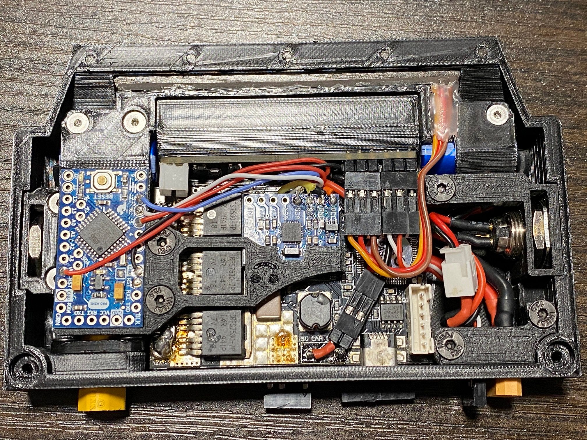
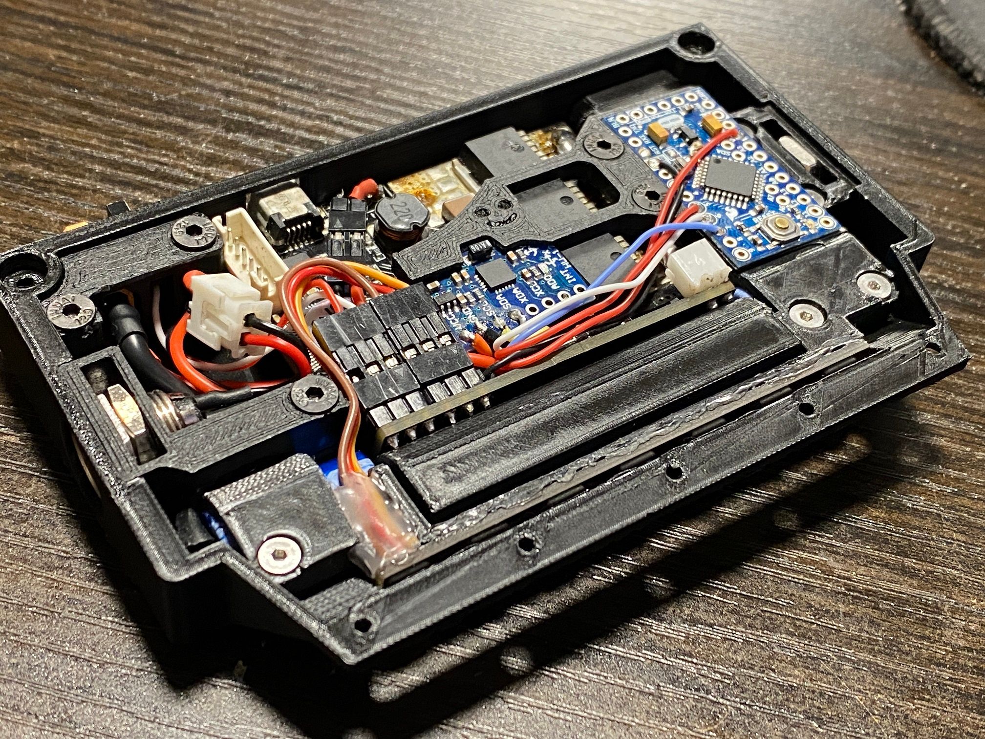
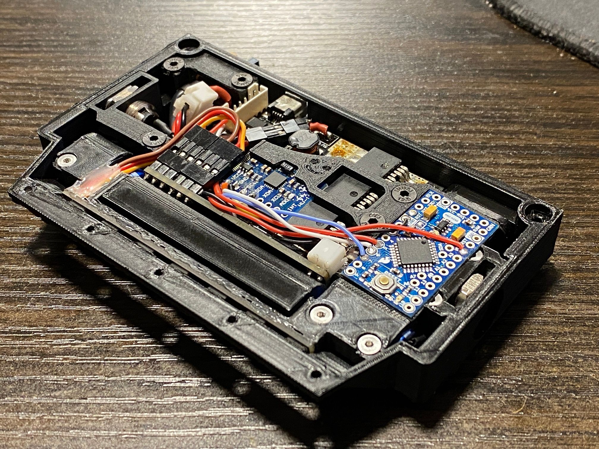
The power button is missing since I need to fix it still. For full functionality I need to wire up the hall sensors to the Arduino to read motor direction but I haven't even written code to operate the lights outside of modifying the stock "blink" code. Not sure how I'll get it to read rotation. Assuming they cycle high and low depending on direction I could just butcher some code together but we'll see.
Still also need to figure out the Power On/Off function. I might need to just make a basic "balance only" circuit and have the mosfets purely as a power function and leave the FSESC to handle LVC and the charger to handle HVC.
-
@lia Absolutely beautiful layout and wiring job on that controller box!
-
@biell Thanks :)
It's so unbelievably dense. Packing it all in has meant shaving parts down by 0.1mm at a time. Got to tidy the led drive wires a little by bundling them into some heat shrink. Been pushing to finish this as I want to feature the XS in a video I've been editing for the past few weeks.@S-Leon Definitely good for learning. Reinforced some things and made me think again about other bits I thought I knew. I can safely say without custom PCBs for the ESC I doubt anything smaller or more powerful is possible at this scale.
-
Just a quick update. LEDs are working, Arduino works and through some arcane magic I managed to resurrect the tiny power button with some
micro-surgeryspells.Haven't actually tested the charger up until this point since the port wasn't hooked up until yesterday. Here it is~
Need to adjust the flash timing on the power button a little but with the example fade code from the Arduino IDE (programmer) it works fine for demo purposes :)
Half scale XLR, half scale charger and it uses a USB C port as the power input... because there is no way I'm doing 230v AC to 16.8v DC in that space! Need to move the red and green LEDs from the charge circuit up to the indicator hole on the lid but that's for another day.
Current code that was used here.
int Wled = 5;           // The PWM pin the Forward LEDs are attached to
int Rled = 6;           // The PWM pin the Reverse LEDs are attached to
int Bled = 9;           // The PWM pin the Power Button LED is attached to
int Wbrightness = 240;   // how bright the Forward LEDs are
int Rbrightness = 255;   // how bright the Reverse LEDs are
int Bbrightness = 0;    // how bright the Power Button LED is
int fadeAmount = 5;    // how many points to fade the  LEDs by

// the setup routine runs once when you press reset:
void setup() {
  // declare pin 5, 6 and 9 to be an output:
  pinMode(Wled, OUTPUT);
  pinMode(Rled, OUTPUT);
  pinMode(Bled, OUTPUT);
}

// the loop routine runs over and over again forever:
void loop() {
  // set the brightness of the pins:
  analogWrite(Wled, Wbrightness);
  analogWrite(Rled, Rbrightness);
  analogWrite(Bled, Bbrightness);


  // change the brightness for next time through the loop:
  Bbrightness = Bbrightness + fadeAmount;

  // reverse the direction of the fading at the ends of the fade:
  if (Bbrightness <= 0 || Bbrightness >= 255) {
    fadeAmount = -fadeAmount;
  }
  // wait for 30 milliseconds to see the dimming effect
  delay(30);
}
Nothing yet for detecting rotation direction, swapping the LEDs from forward to reverse or anything else really, just enough to get it working.
-
@lia Down to the charger block, the attention to detail is masterful.
-
@biell Couldn't resist, thinking of doing the Deep Shack stand too but that'll require me to learn steam bending and find a good way to do it ;)
I have an initial version of the charger before I redid the design meaning there's a little paperweight laying around that is too nice to throw away with the rest of the prototypes. Unsure if I should put together some of the better prototypes and give them away or something.
-
Assembled the new controller housing. Now on V12 and decided to show how it all goes together just to emphasise how dense this is. At some point I'd love to have these printed on a resin printer so the layer lines are less noticeable and the details come out cleaner. Too expensive right now though so at worst I might see if I can pay someone to print some parts on theirs.
Below are all the parts of the XS controller. Some pre-assembled into their modules like the charge port and power button.
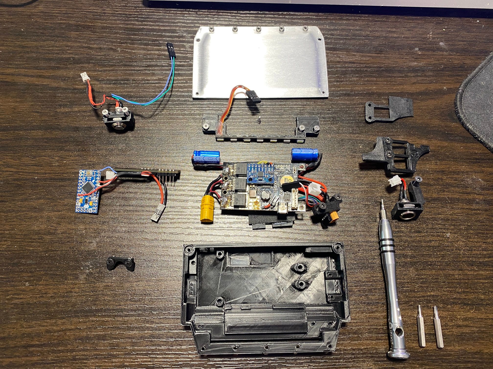
First step is to mount the FSESC and get the footpad/motor sensor wires aligned then use the m2 screw to pull them through the holes and secured to the case. Capacitors will seat in 2 cradles either side of the handle cavity while the motor connector slots into the triangular hole.
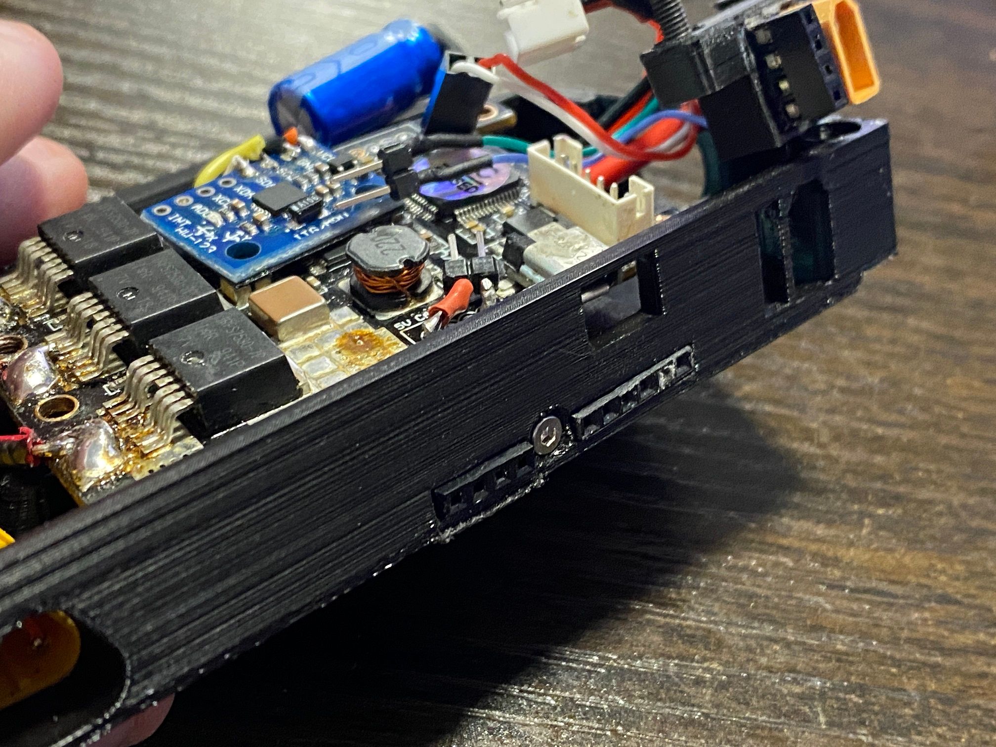
Best to slot the lower IMU mount in between the FSESC and IMU to keep it mostly aligned. Also a good time to secure the power ports which will also hold the FSESC in place on the lower right tab.
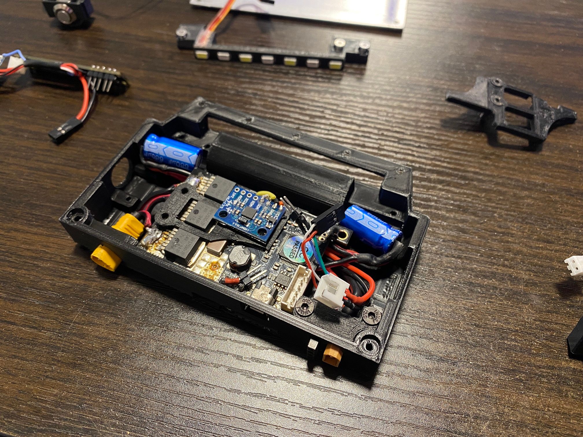
Secure the motor connector with the small bracket that traps it in the opening.
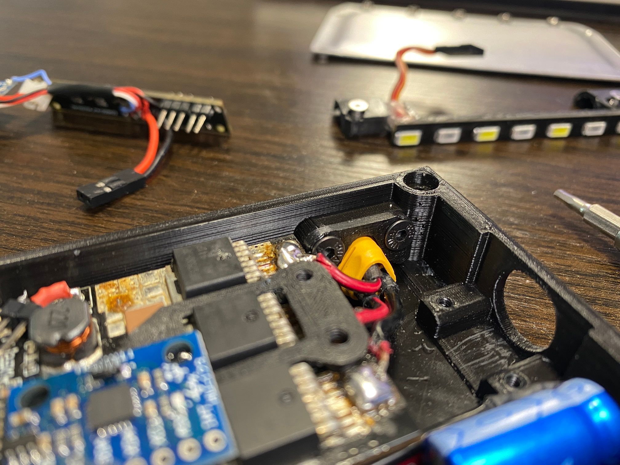
Next the power button needs mounting.
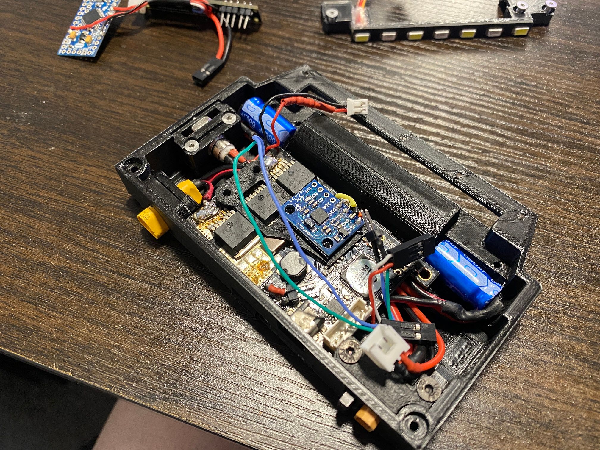
Route the blue and green wires from the power button around the edge then secure the upper IMU mount in place. The IMU is now secure while also holding the FSESC down and stopping the blue/green wires from the power button for moving out of it's desired route.
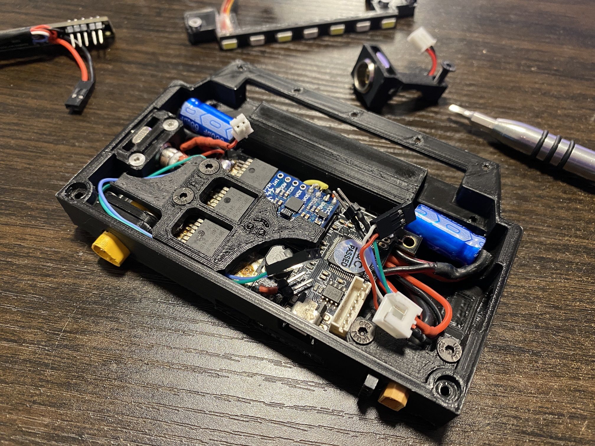
LED bar can be mounted which will also secure the capacitors in place.
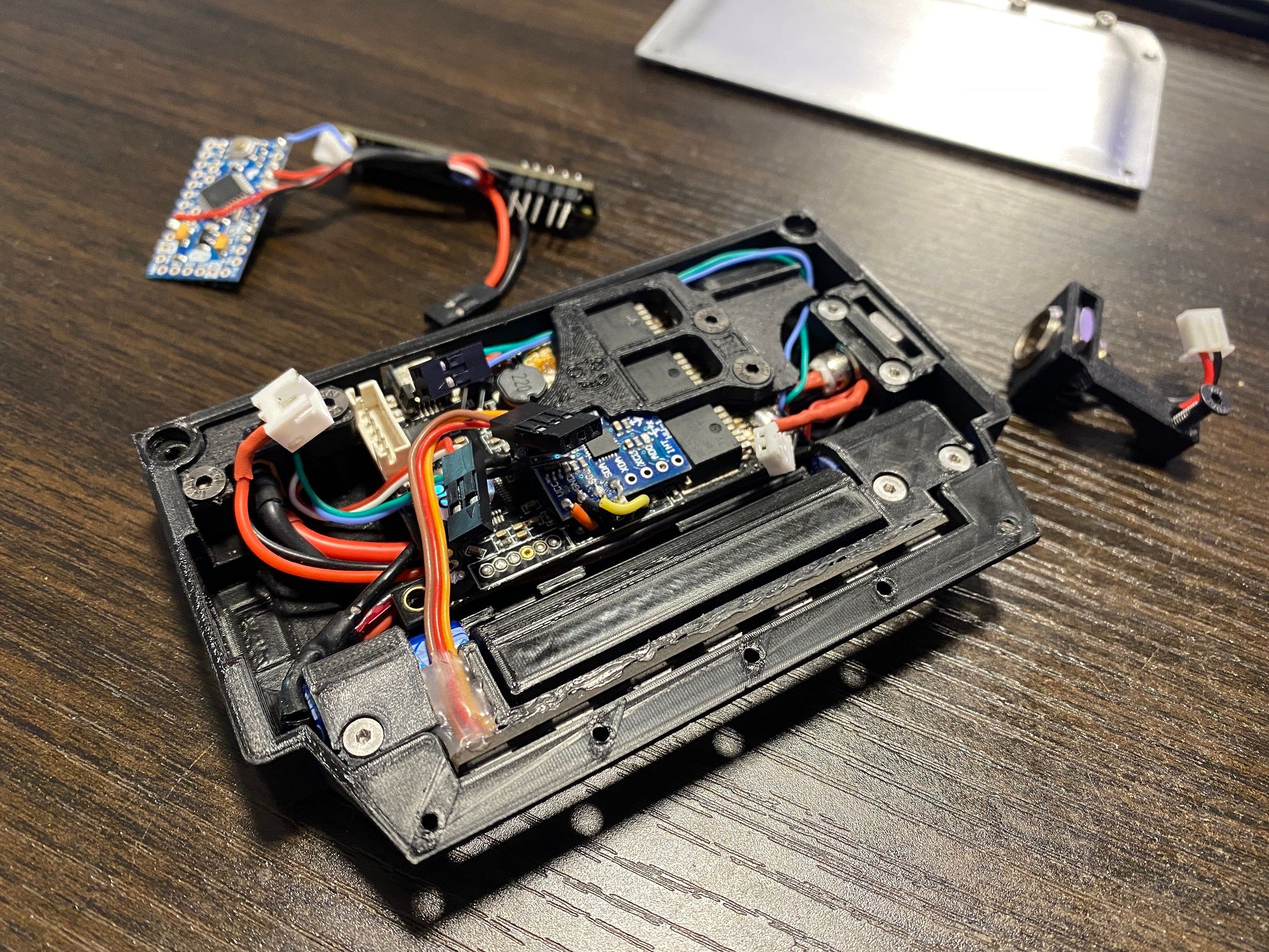
Charge port can be mounted in place which locks the capacitor wiring in place and also holds down the FSESC on the top right corner now having it secured on all 4 corners. Charge port can be connected to the FSESC module with the corresponding port.
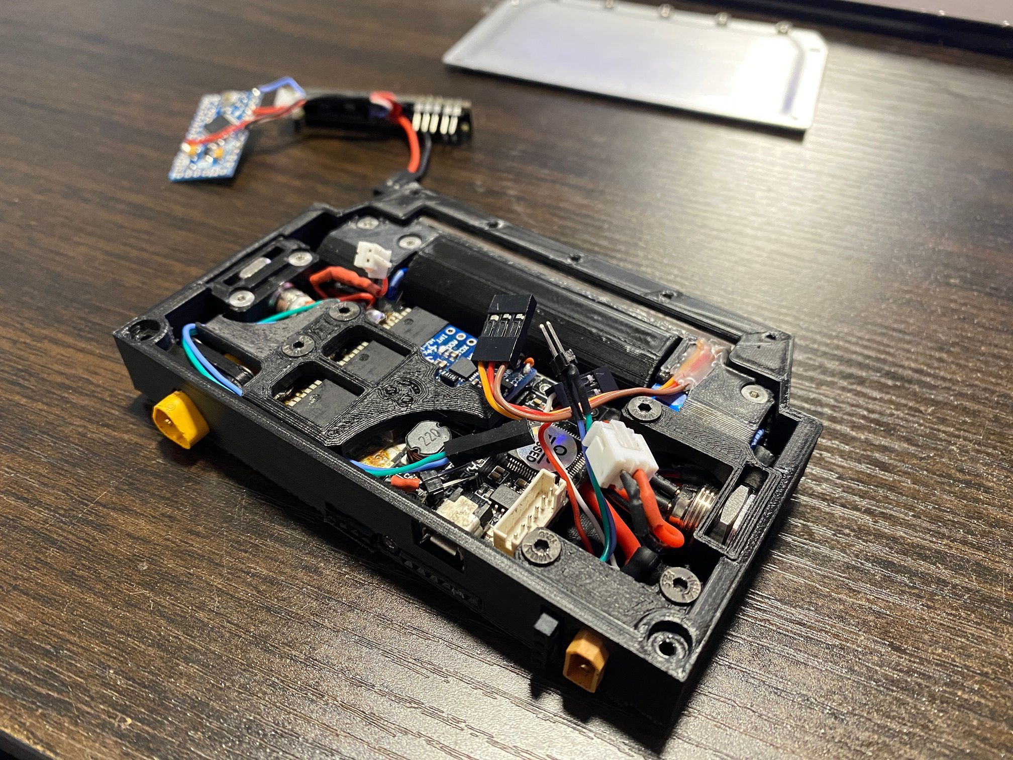
LED driver module can be slot behind the handle cavity which press fits into a mount lower down. All connectors can now be fit onto the appropriate points.
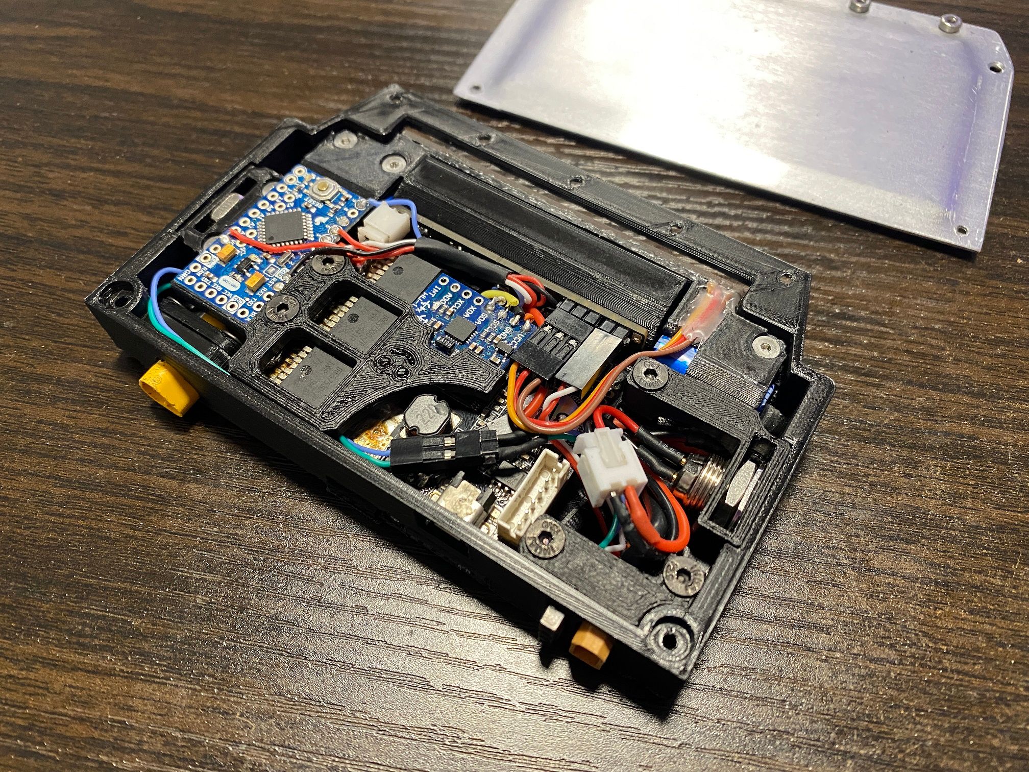
The lid can now be secured :)
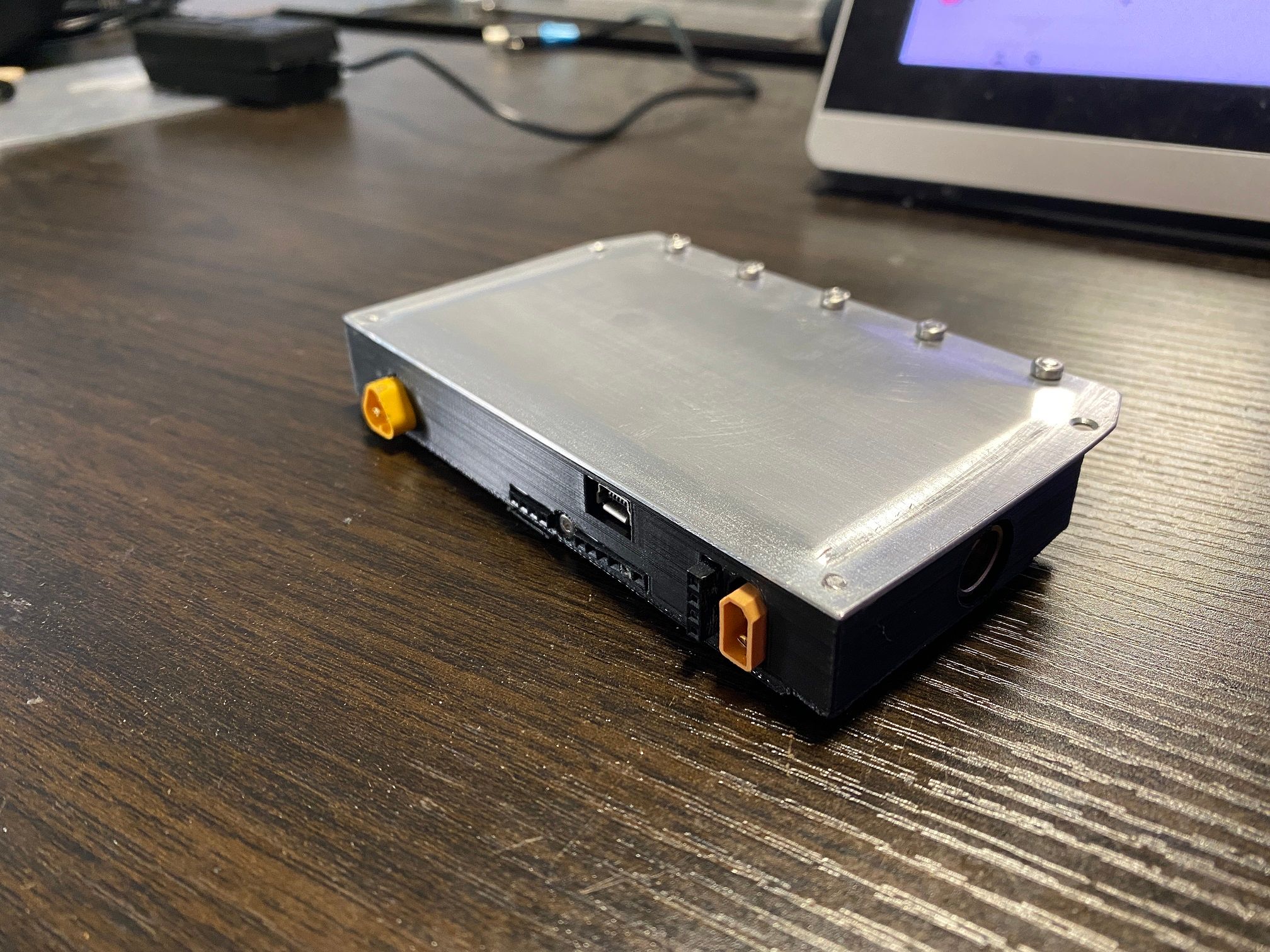
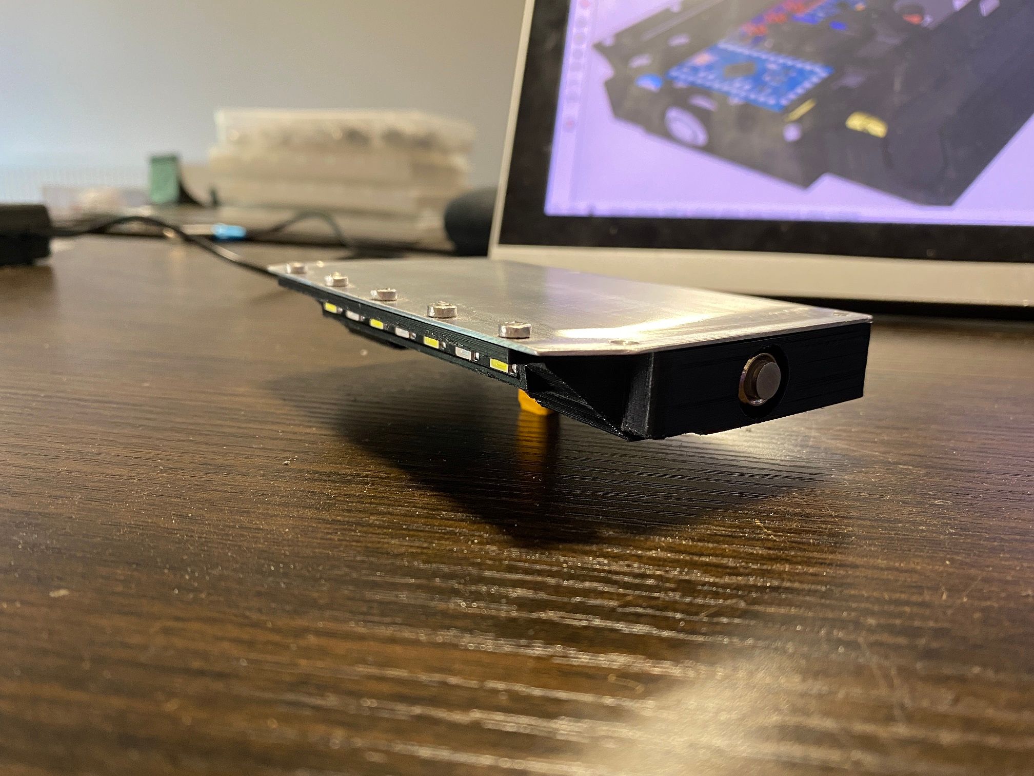
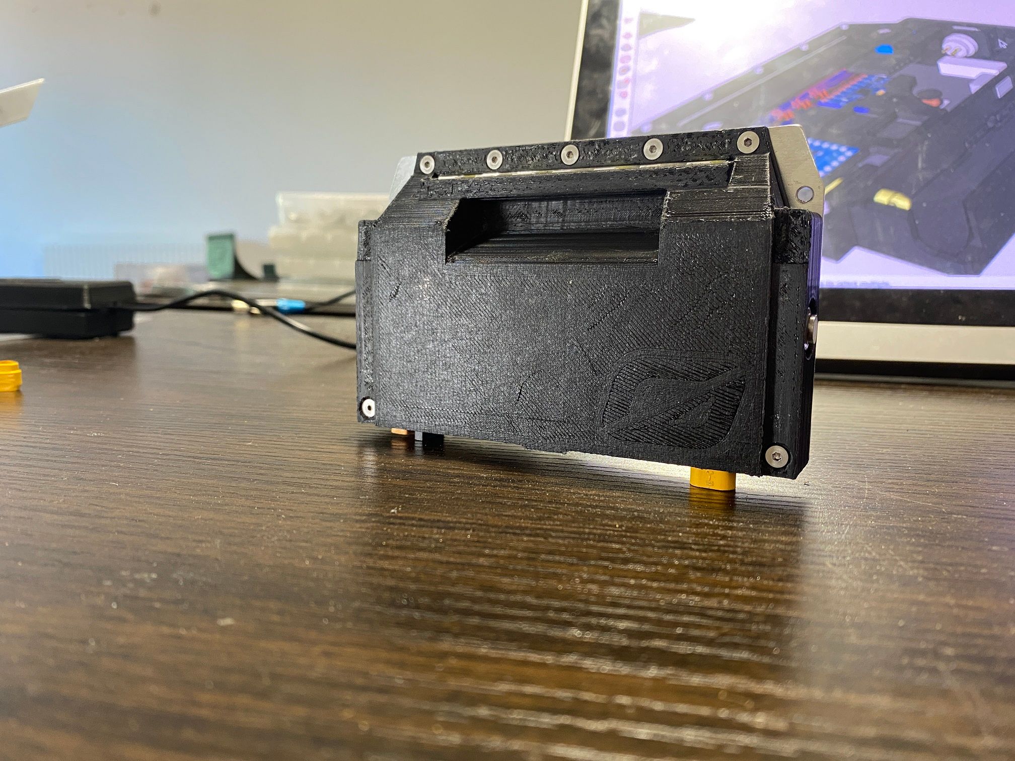
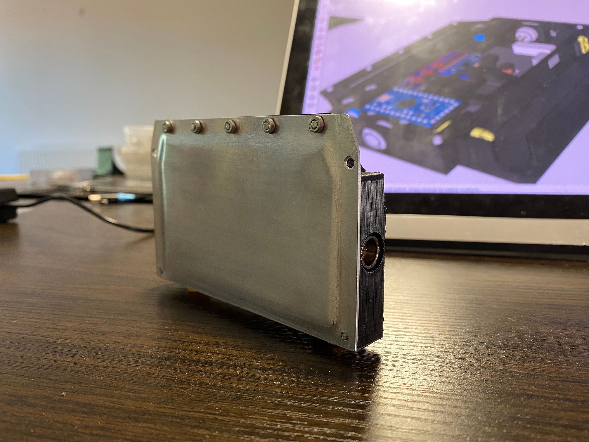
That should be the controller done. One really cool thing I noticed when testing later is the handle is warm when powered on. This is because I mounted the LED driver board right up against the handle cavity which gets warm (30-40c I guess, above ambient but not hot). Imagine if the other models had this, winter wouldn't suck so much when having to carry the board ;)
As a bonus here's the XS rolling fully by itself. No strings attached, no external power. Just me pushing it around and letting it return :)
I didn't capture it but I did miss catching it on one throw meaning the XS rammed my knee. Gonna bruise as it was going pretty fast all things considered. Total weight is 2KG so it's not just a gentle tap when it's going for you.
Left the lid off for the testing because I wanted easy access to check temps and see smoke ;) As I've not added the footpad sensors there are only 5 fail modes which'll stop it from endlessly trying to balance.
- Batt too high
- Batt too low
- Overcurrent
- Roll angle out of range
- Pitch angle out of range
With that in mind when I want to stop it balancing I just roll or pitch the nose till it stops. Balancing only resumes when the board reaches near level which if paired with the footsensors will function as expected :)
Hopefully I'll be able to record some shots tomorrow and finish a vid I was working on. The XS is meant to features in a few scenes so been trying to get to this stage in order to get those last shots.
-
2 kilograms and this 3D-printed tire keeps up good work holding grip at your carpet? Outstanding motion!
-
@lia -- Your jaw-dropping XS is certainly a rambunctious little rascal!
-
@sirgu It's doing shockingly well considering that TPU isn't very grippy. Definitely need to cast a tire from rubber instead.
Kind of amusing how if I add any sort of instability on the throw it keeps it on the return. PIDs are really basic so might explain the lack of damping.
@S-Leon Rambunctious indeed!It's definitely starting to take on a personality or an attitude.
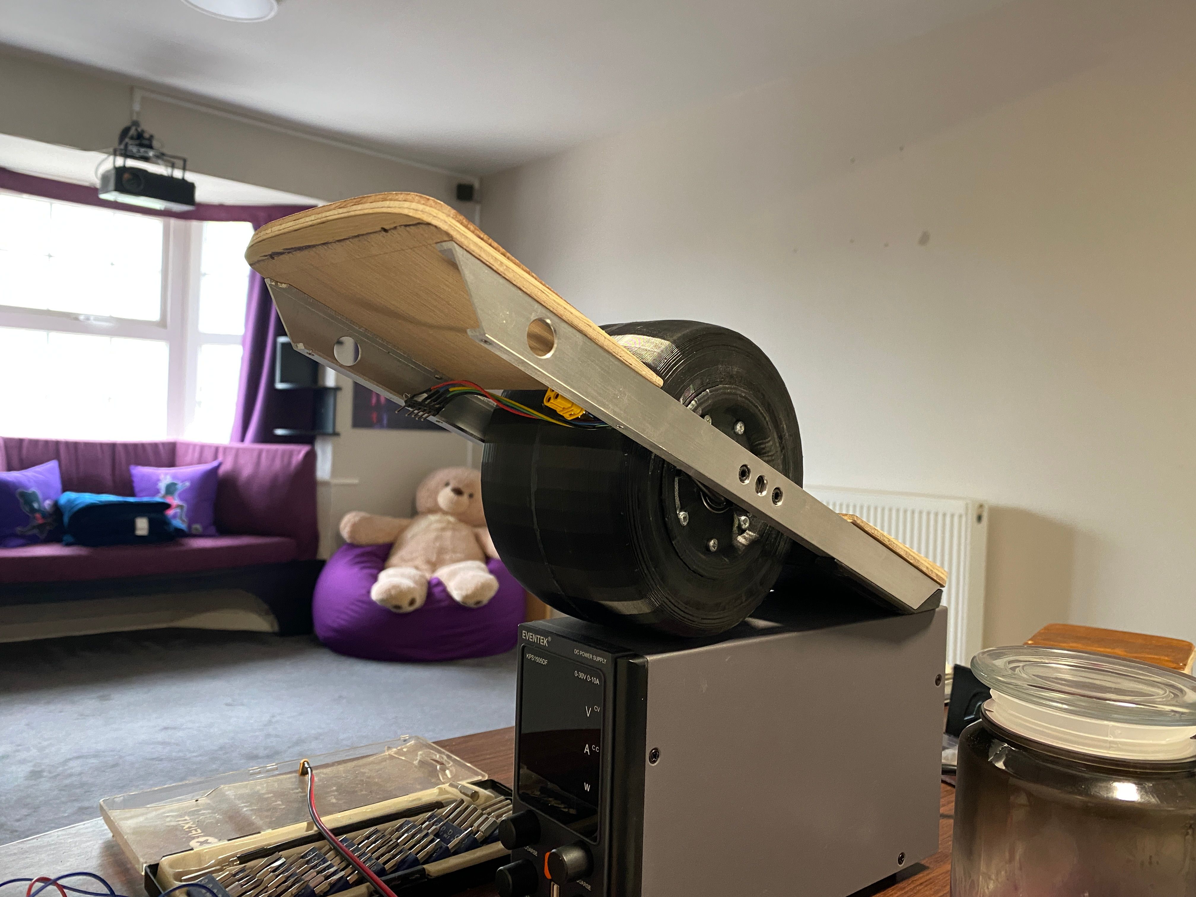
One pic I took of it a few days ago actually reminded me of a pic you took of your Plus when showing the missing battery section. Just the un-anodised rails, pad and cavity underneath.
-
I've been holding back, got some bits done that I'm particularly proud of but wanted to wait till after releasing a video before sharing ;)
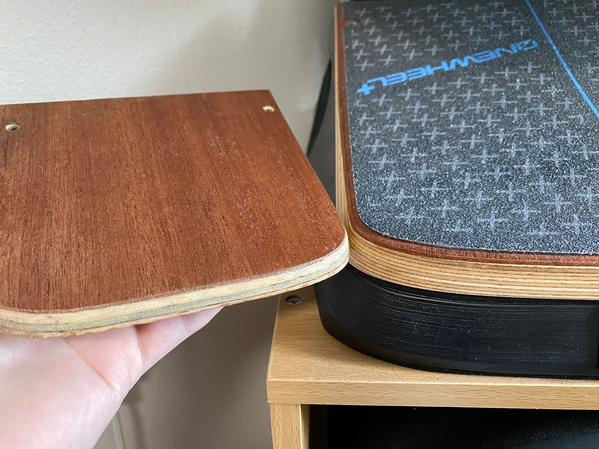
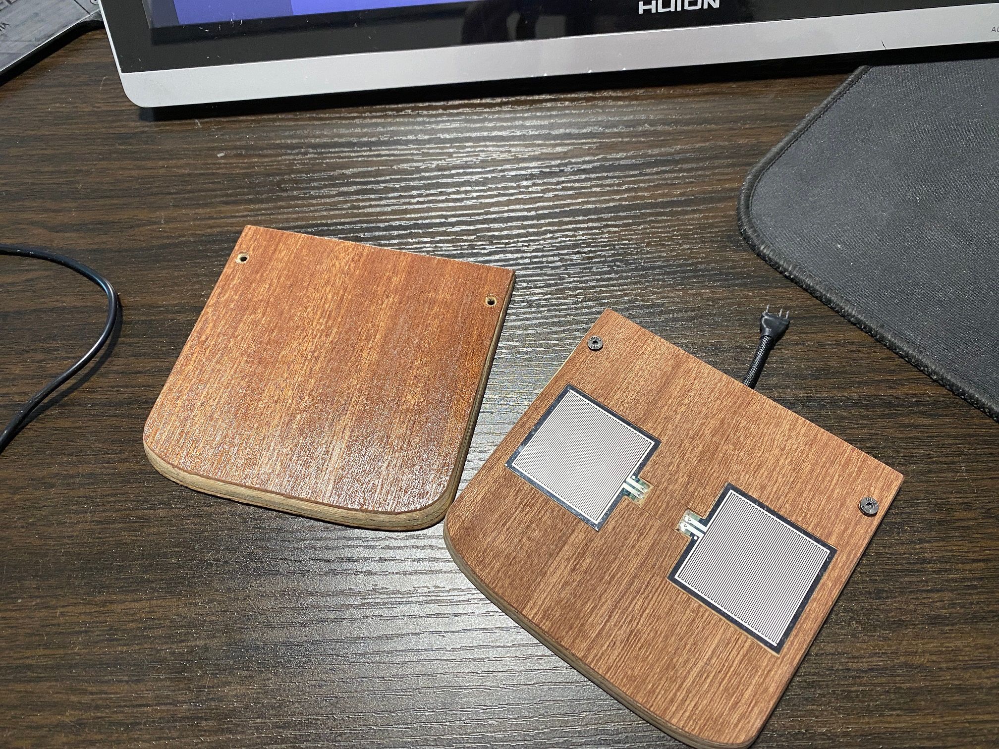
The footpads, I cannot for the life of me remember who suggested this so please feel free to remind me. Someone suggested the footpads should have a different wood layer for the top piece rather than me cheating and using a coat of varnish to artificially make the alternate top layer. It was a very good suggestion and whoever made it deserves a gold star x
However due to the size I was able to instead get away with using some veneer to achieve this and the results are great. So much better than faking it with varnish. I actually still don't know what type of wood it is though since I bought a cheap pack of assorted off-cuts and chose what looked right assuming it'd be darker after some clear coat (it was, more on that later).
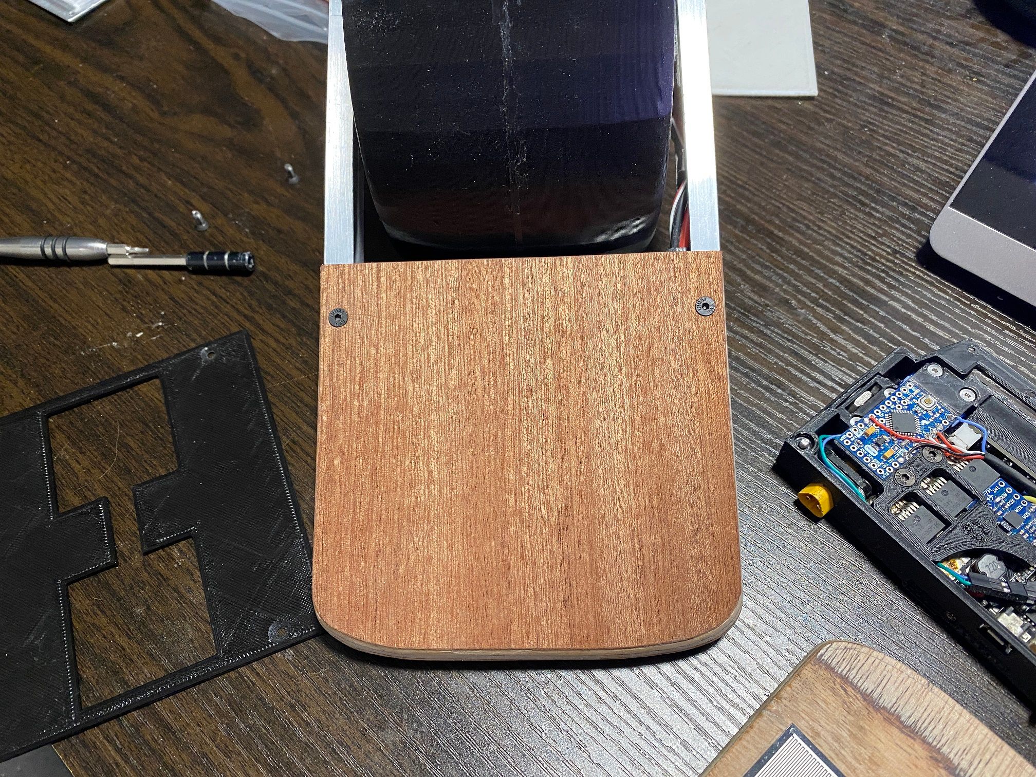
Looks good so far, still needs the clear coat however I wanted to also get the front done andalso mount those little sensors.
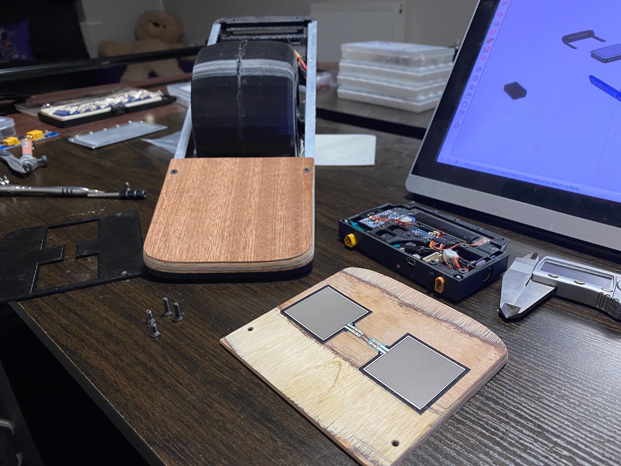
Reminiscent of the V1 sensors hat didn't occupy the entire footpad. To make sure the griptape didn't bulge because the sensors were taller than the veneer I cut out where the would sit and then placed that on the pad making the sensors barely sitting proud of the surface. Enough to function under griptape (tested with a sheet of paper) but not so that you can clearly see where the pads are.
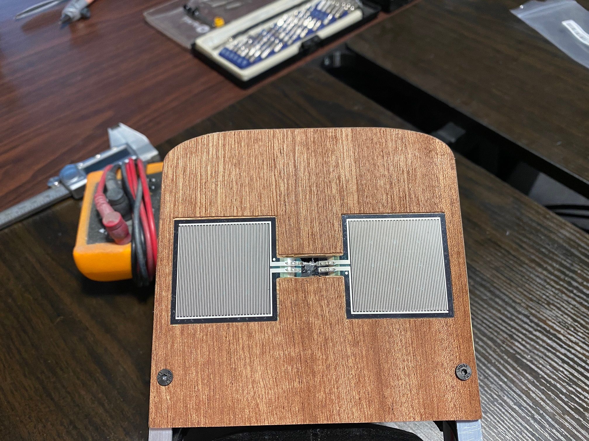
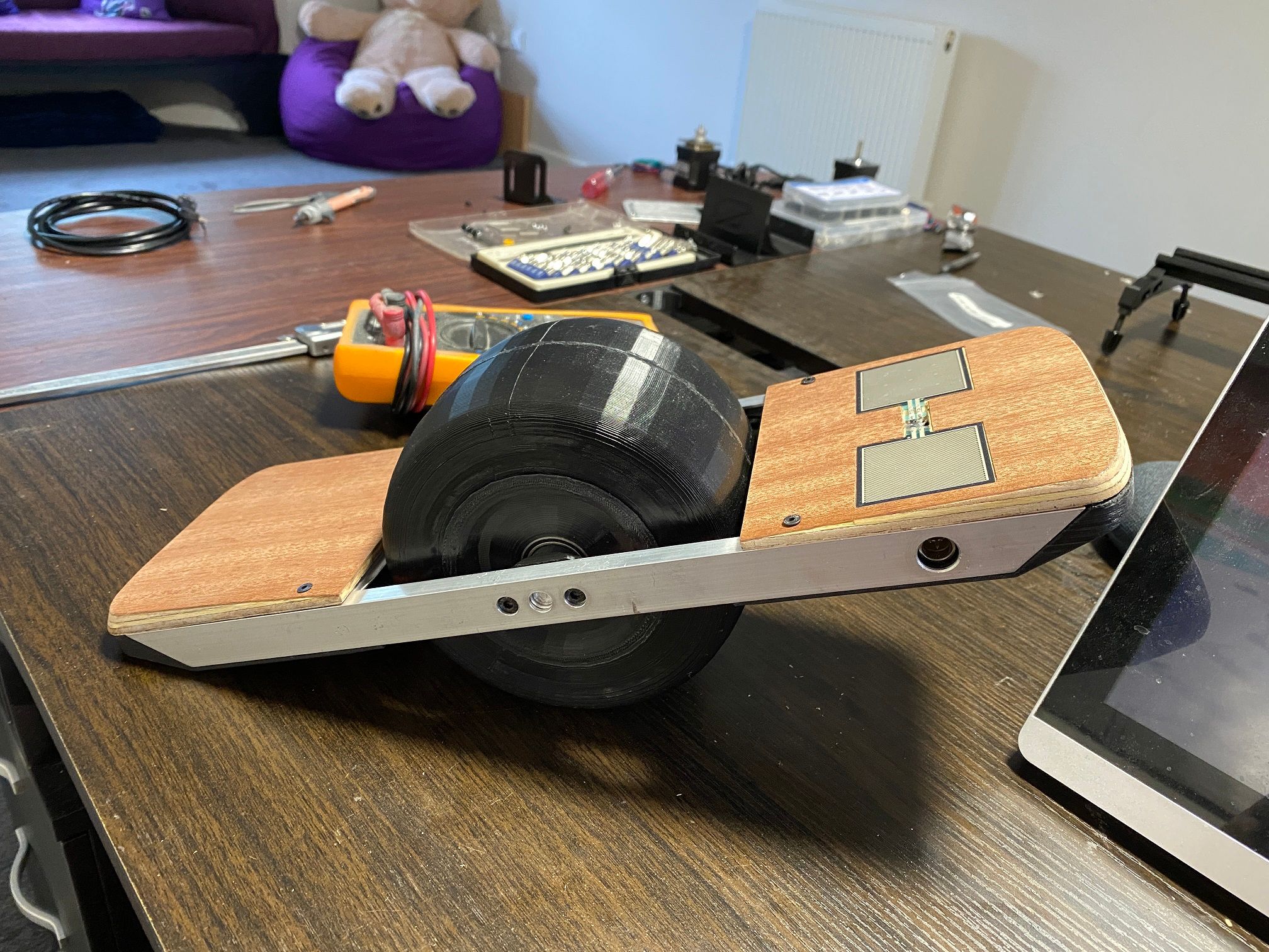
Lastly came the clear coat. I haven't done the front pad yet but the rear came out so well I'm eager to do it.
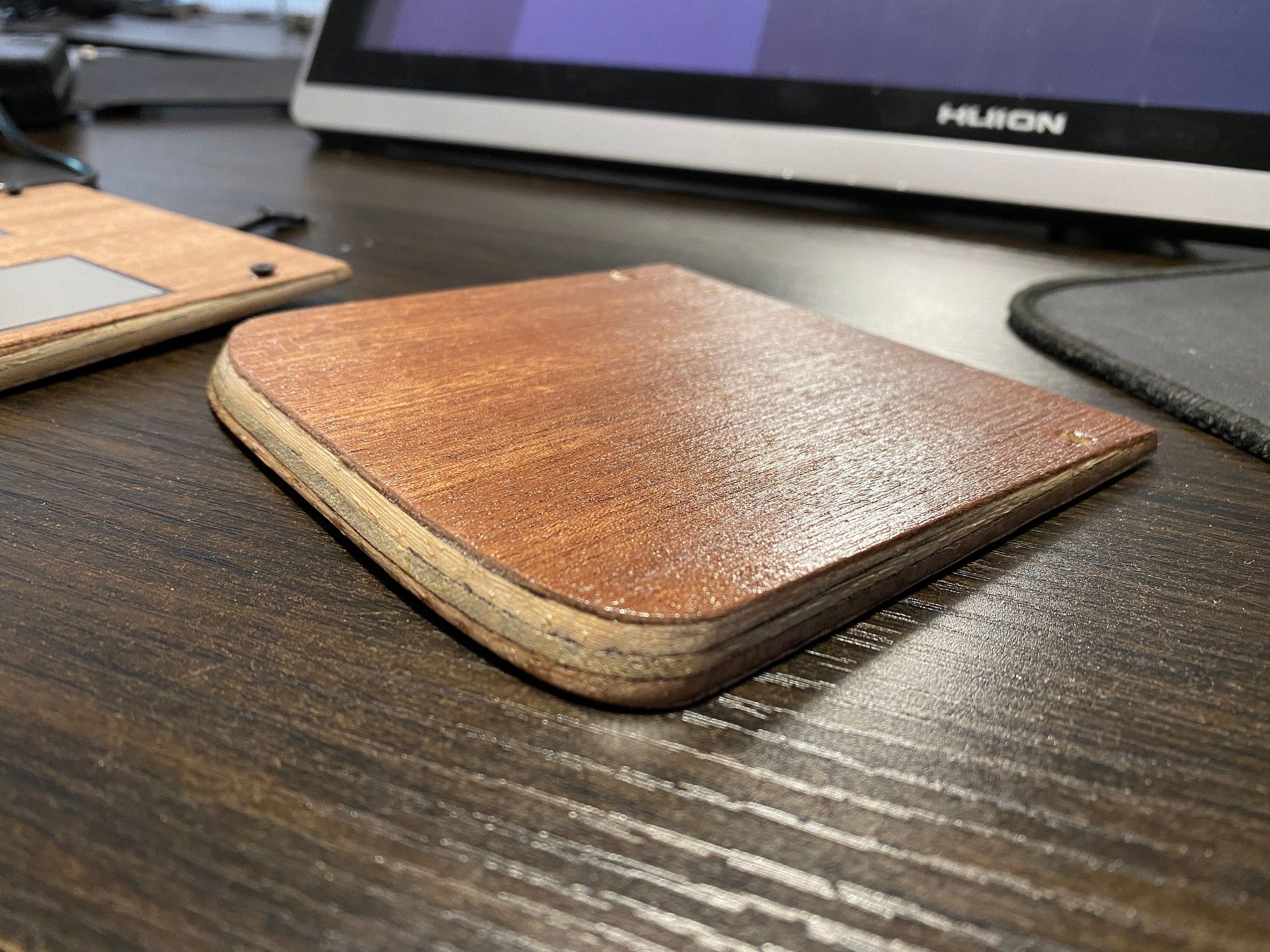
You'd think I knew what I was doing, it's almost perfect (ignoring the ply density)
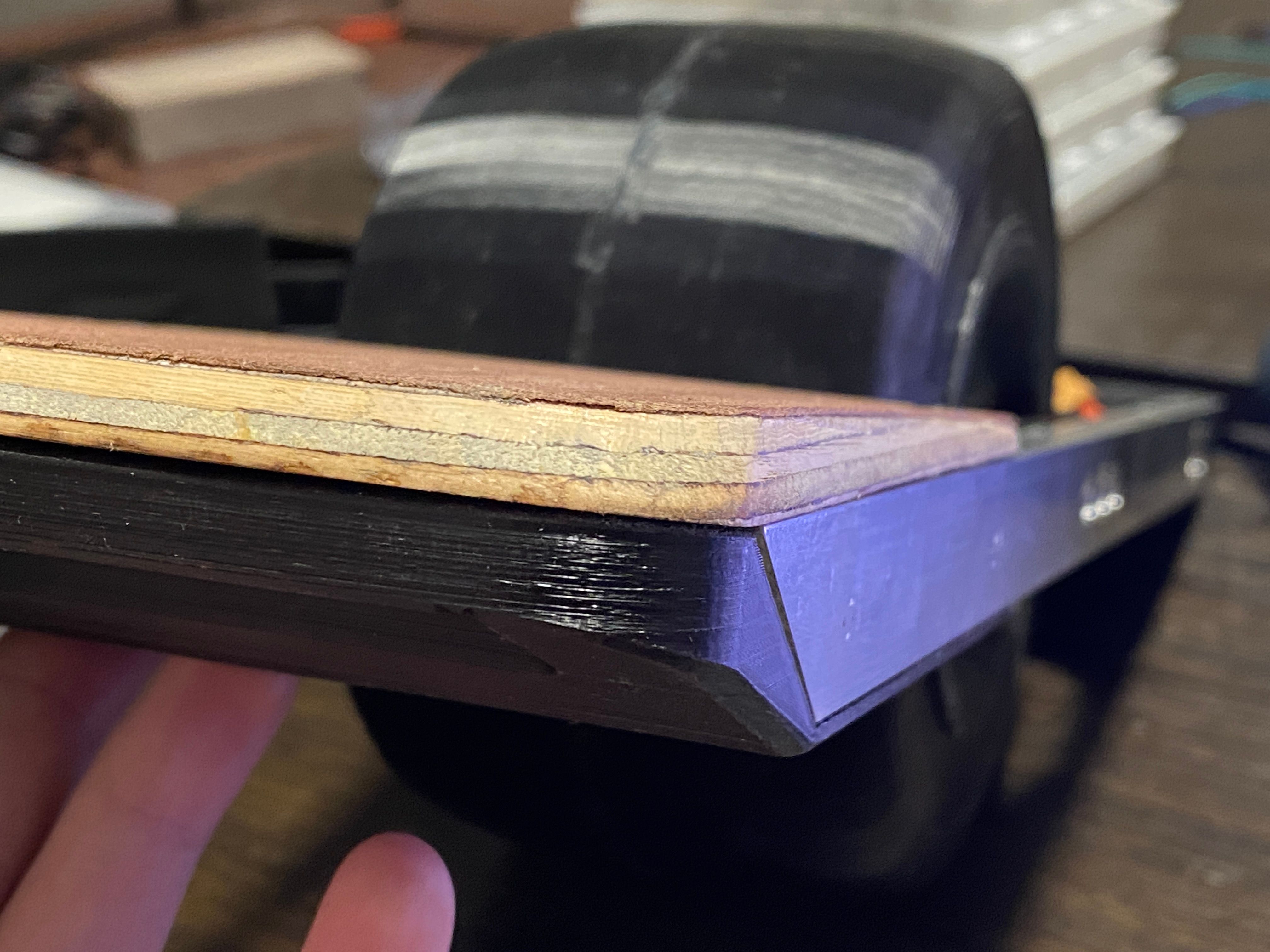
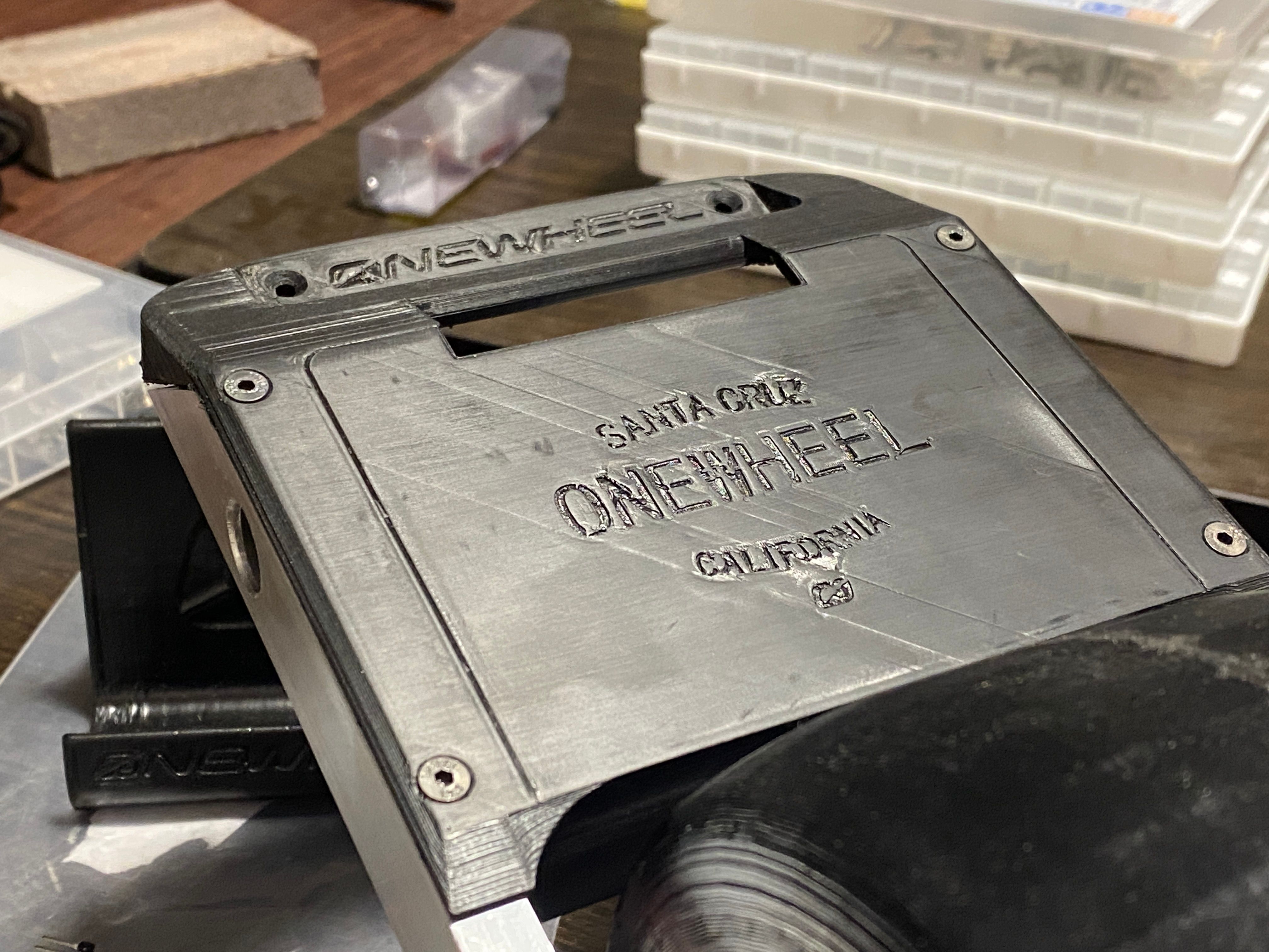
As an added bonus I redid the front bumper to remove the pillowing effect caused by the infill pattern on the last one. After a light sanding it's buttery smooth. Almost looks like it was done on a resin printer. Still want to resin print these though for the added detail retention on the lettering.
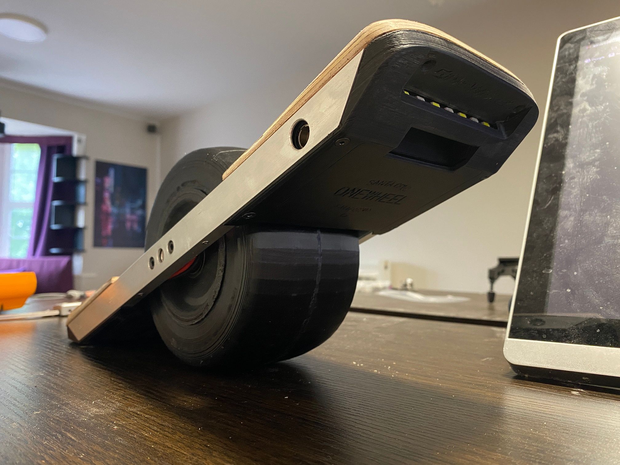
To see my playing around with it working there's a few sprinkled in clips on the video I mentioned earlier.
It's so stupidly fun to just place 2 fingers on the pads and feel it move once level. Nothing, not even a video can translate the stupid joy I get letting it roll around. I made noises I didn't know I was capable of, which thankfully will never leave these walls ;)
-
Few more updates :D
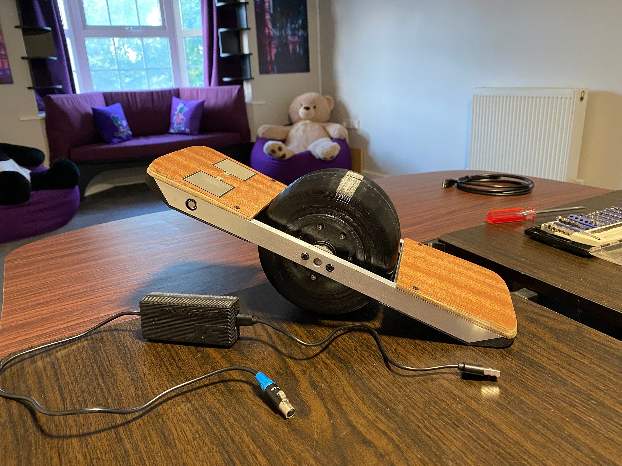
Finally gave reddit an update too, of course here is where all the best pics and info is though :)
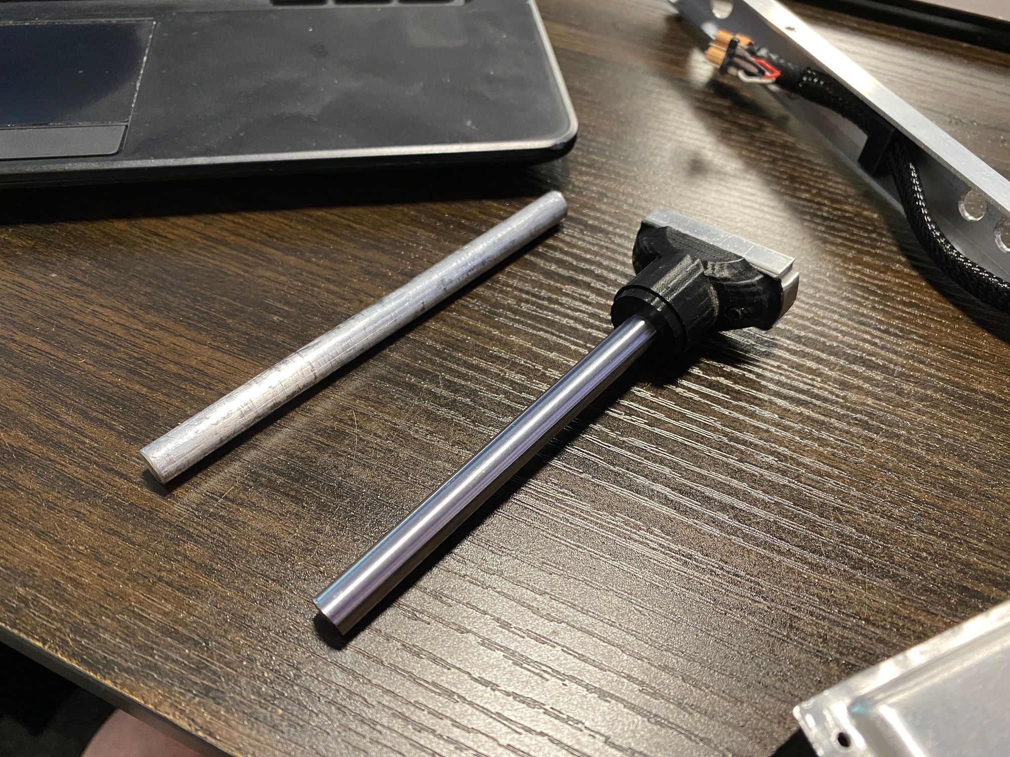
Replaced the axle with a steel one. Had a feeling the aluminium one might bend which would probably destroy the bearings and motor. Was too scared to use my angle grinder so spent like 20 minutes with my little dremel cutting through 8mm of steel bar to get a 115mm long axle. Worth it though, look how shiney it is compared to the scuffed up oxidised aluminium one.
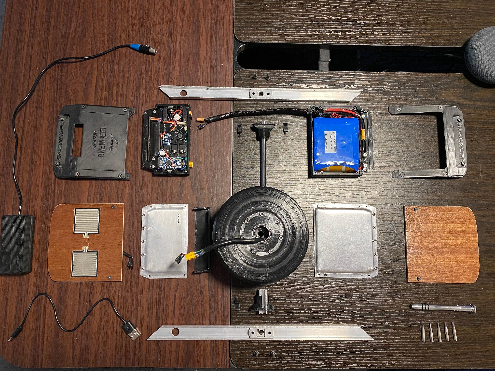
All in bits down to the major components this is what it looks like.
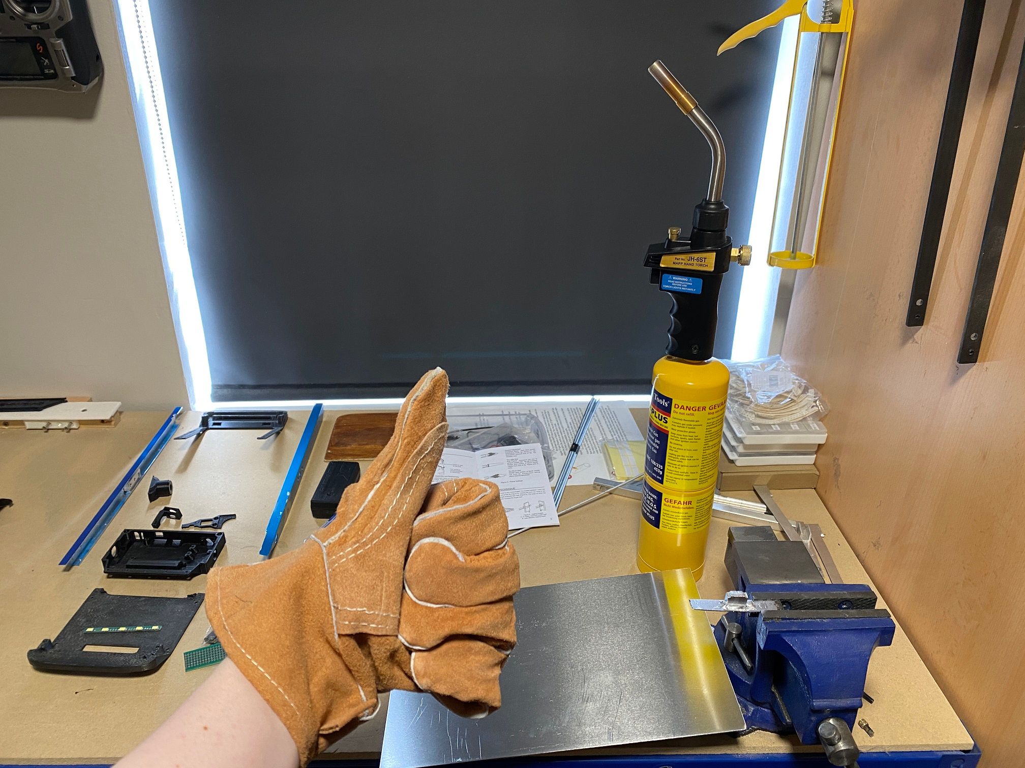
Worked up the courage to try the gas torch today with the brazing rods. These rods melt real quick and I haven't yet mastered the finer touch like I have with normal soldering so although I didn't burn myself or explode the can I'll instead JBweld the axle block to the rail. Tried to do it and it got messy D:
I wish they made smaller gloves too. These gloves are huge... like... do they come in women's sizes lol. I'll keep practising so I can continue the W-Rails.
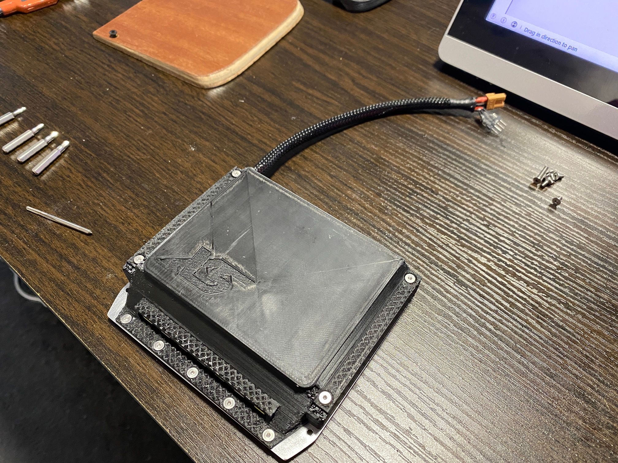
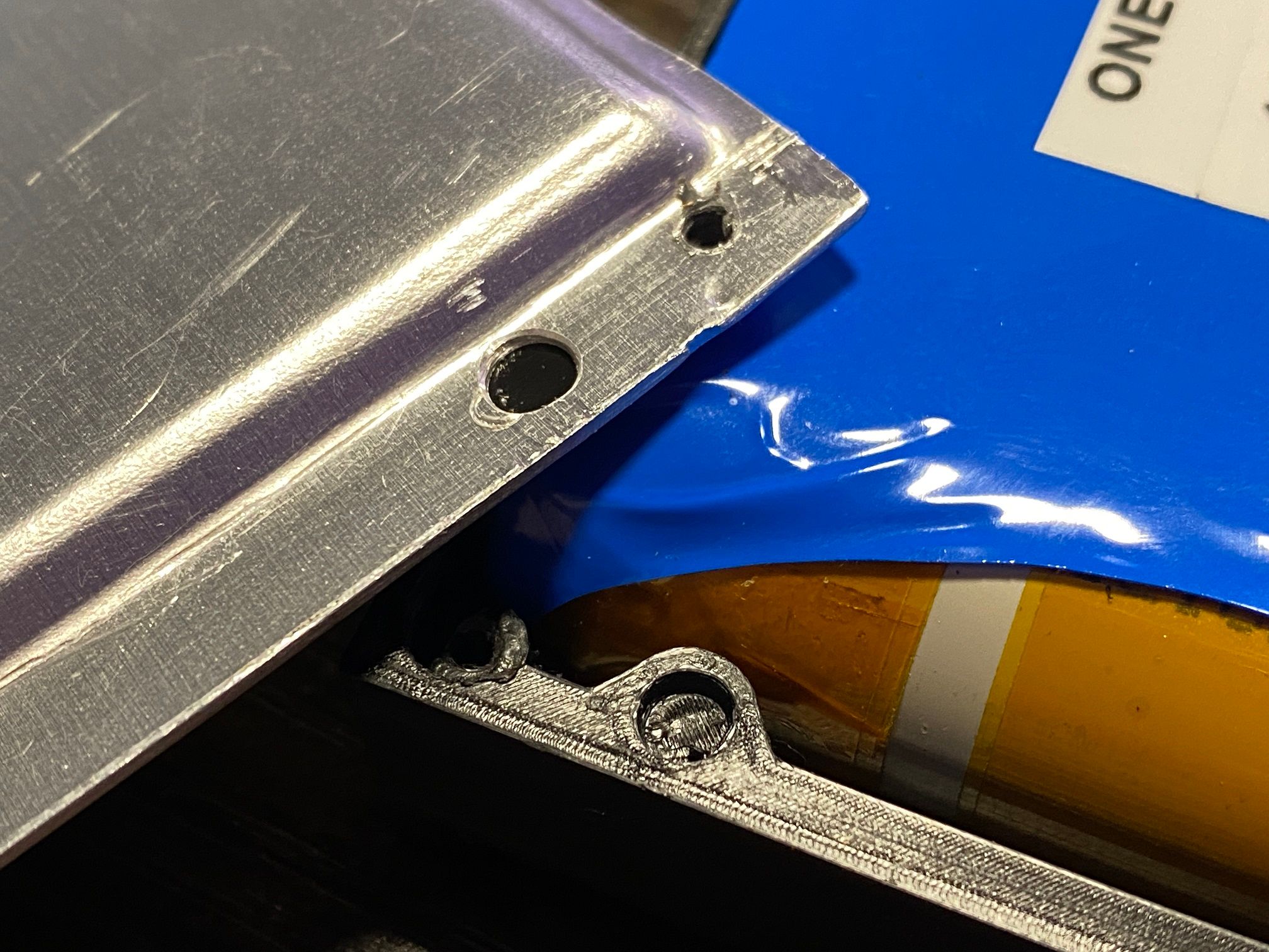
Redid the battery housing again, this time to make the underside prettier and to add some cups to stop me long-screwing the housing with the footpad screws.
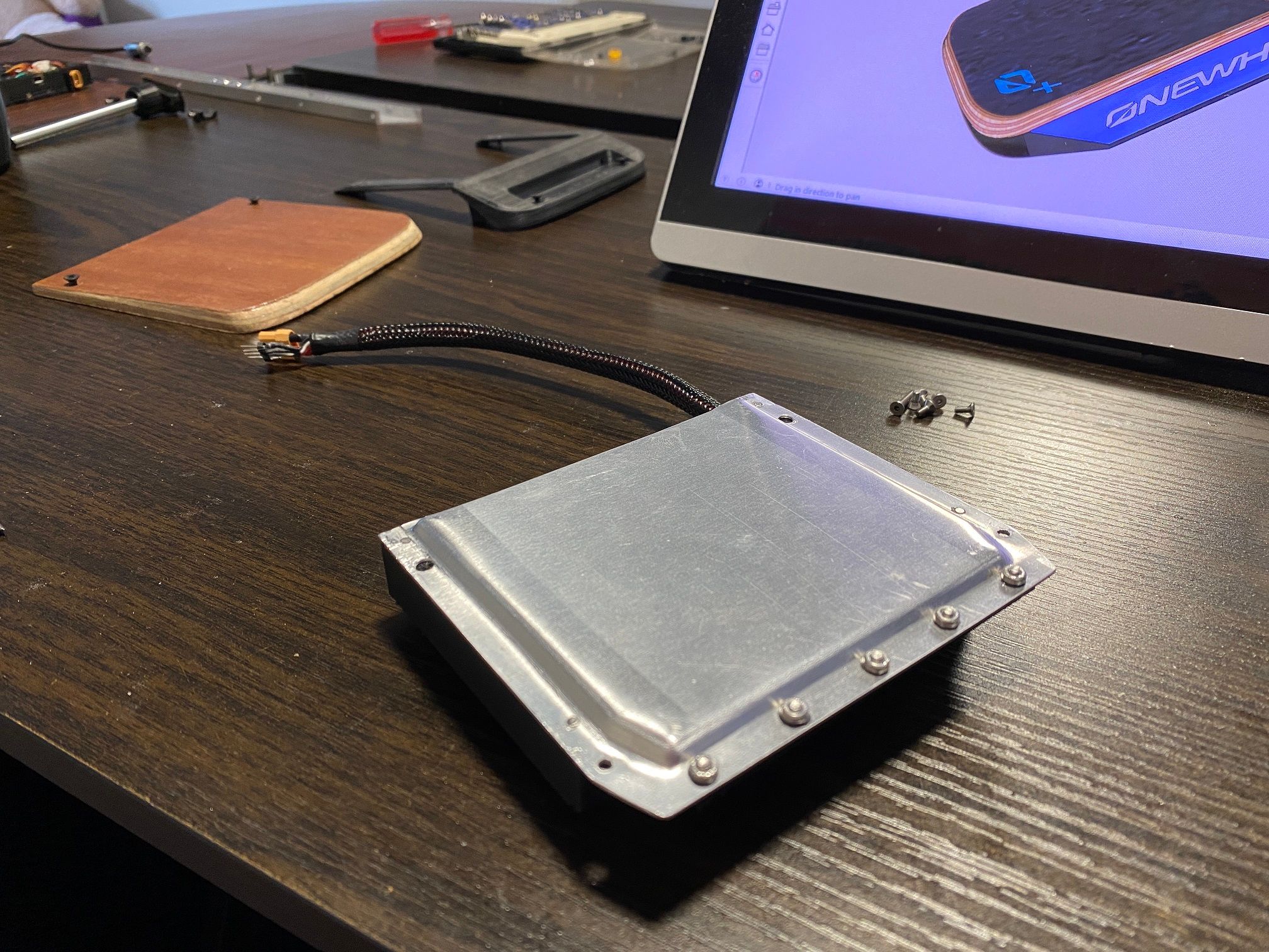
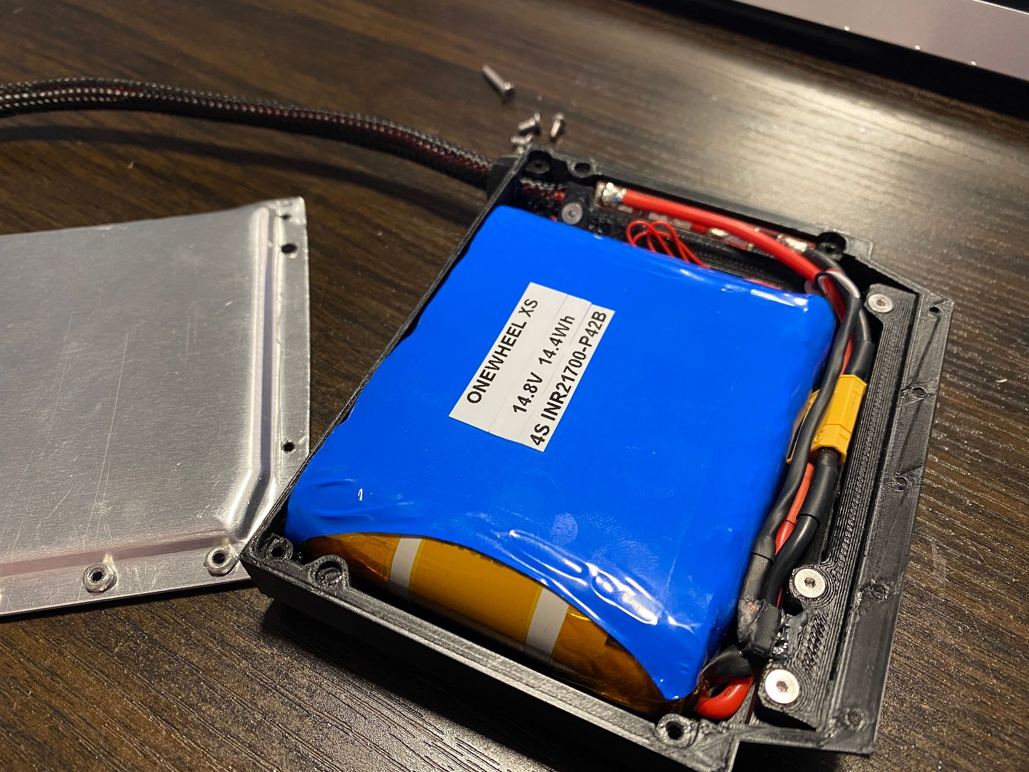
Totally replecated the same choice FM did with the battery lid because I wanted to and not because I didn't want to perfectly shorten the screws >.>
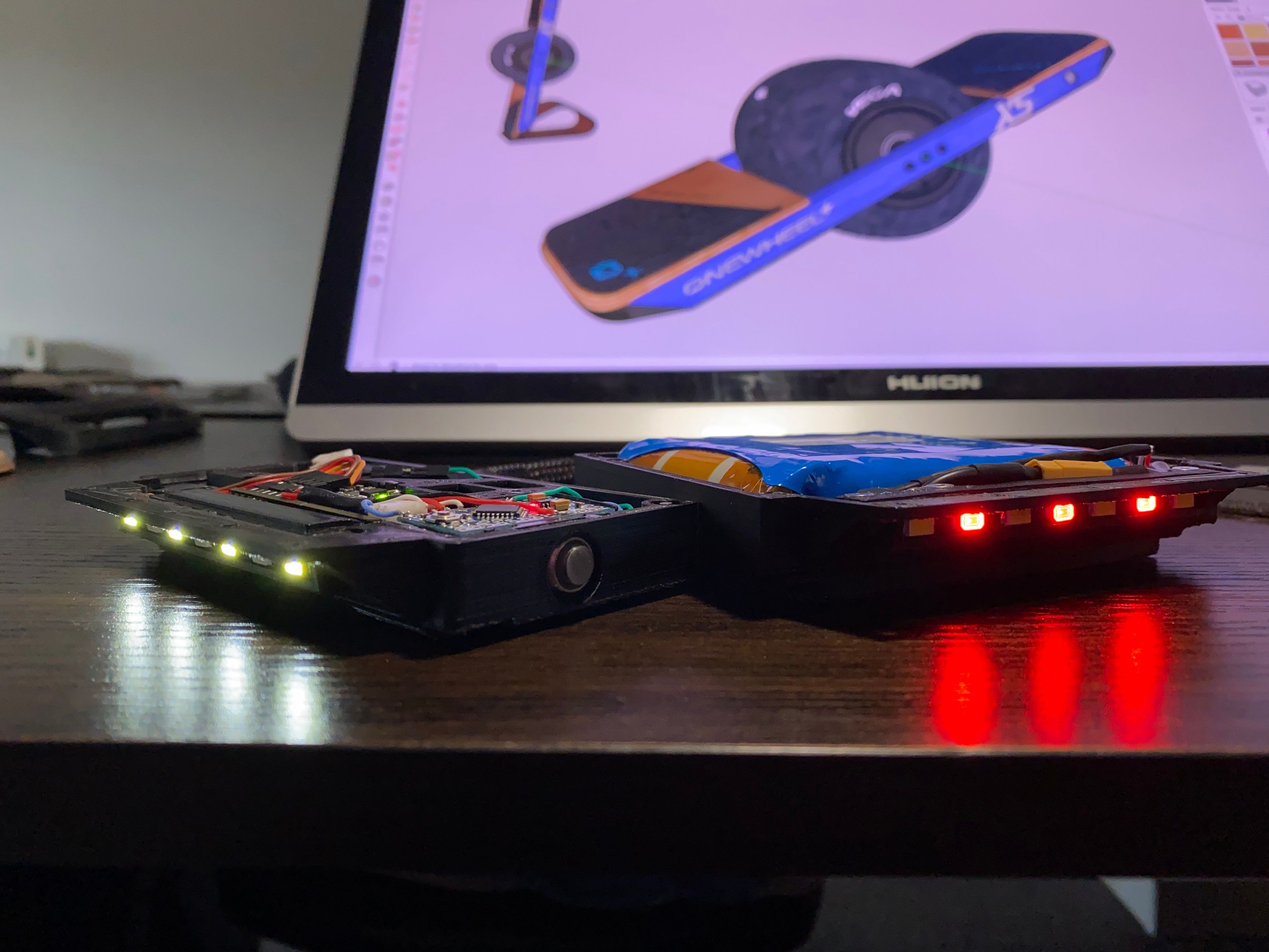
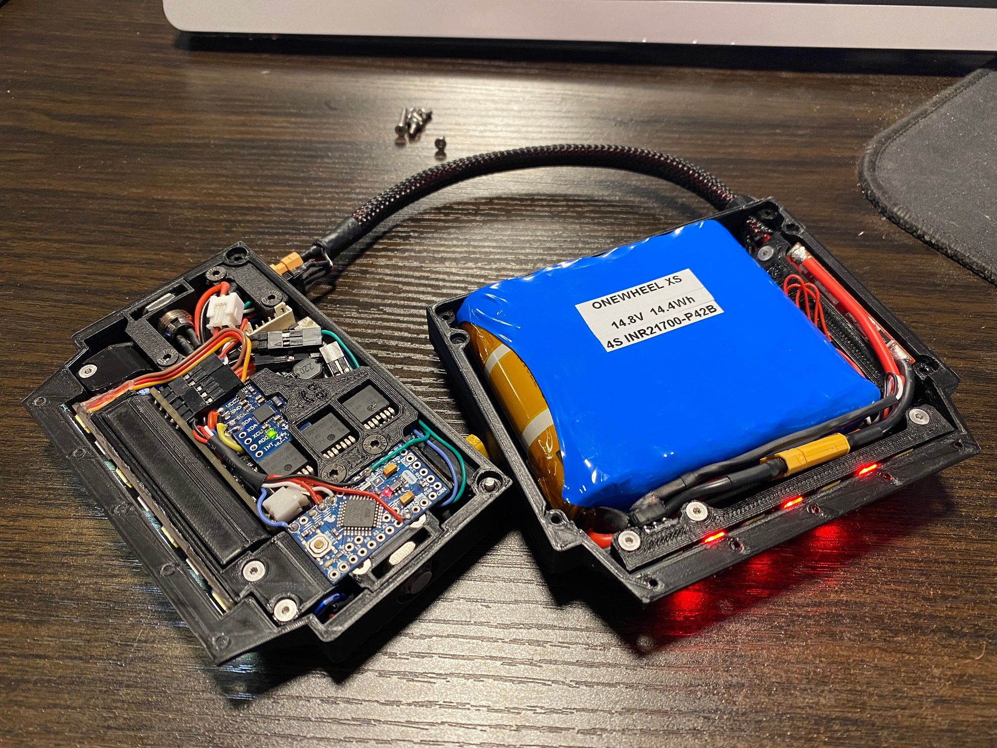
Got a nice pic of the 2 boxes plugged in next to eachother. Sadly the power button LED has died so I'll need to wait for another one of those to come from China :( Can't be too sad though when I have this eye-candy at my fingertips.
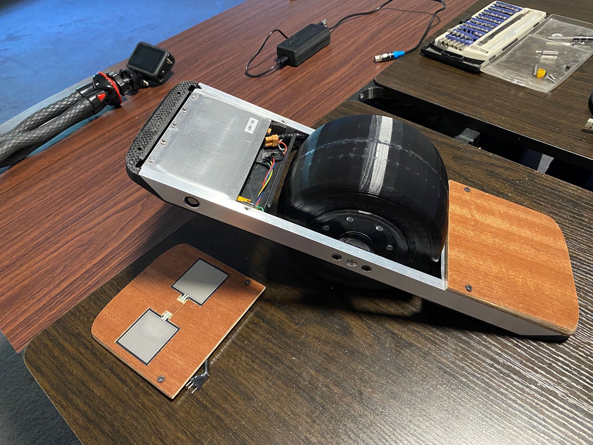
Coated the front footpad, sadly some got into the left pad somehow. I managed to remove lot of it with IPA and squeeze it out but there is now a noticeable dead-ish zone that isn't as sensitive. Woks fine but makes finger riding more difficult.
Final versions of the bumpers prior to hopefully getting them resin printed sometime look real good.
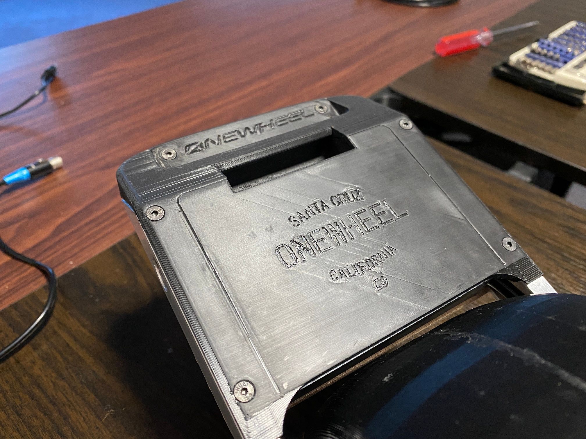
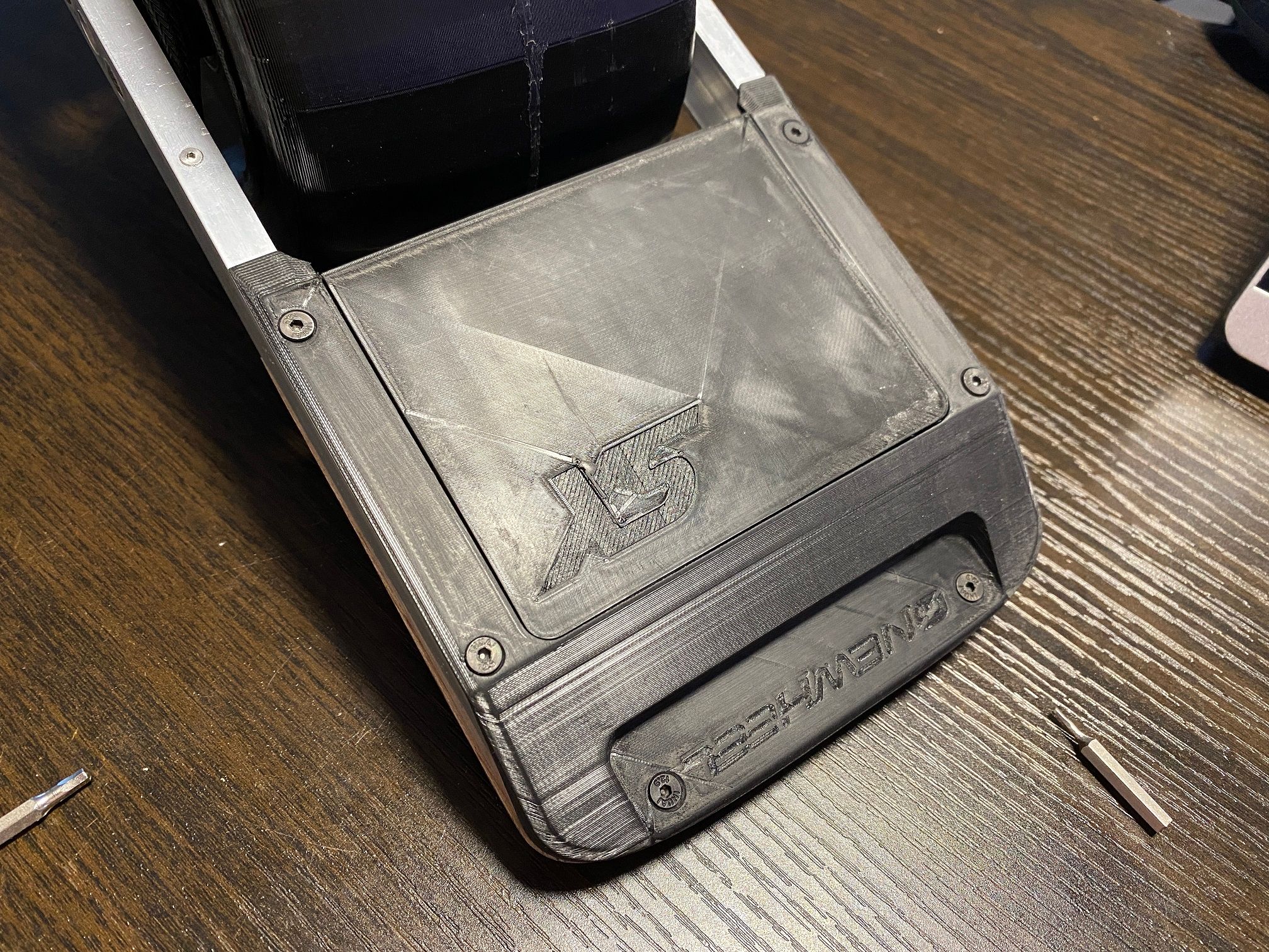
Finally have some more CAD renders :)


-
@lia -- A non-vital shell of a "model skateboard," seven inches long, that looks remarkably like your XS is being marketed by Matthew Shumaker of Tech Rails.
Edit: In the comments on Matthew Shumaker's post on the Tech Rails facebook group, @Lemur (as Fai Leong) posted a photo of a hand-sized XR he built two years ago. @Lemur, please share it here!
-
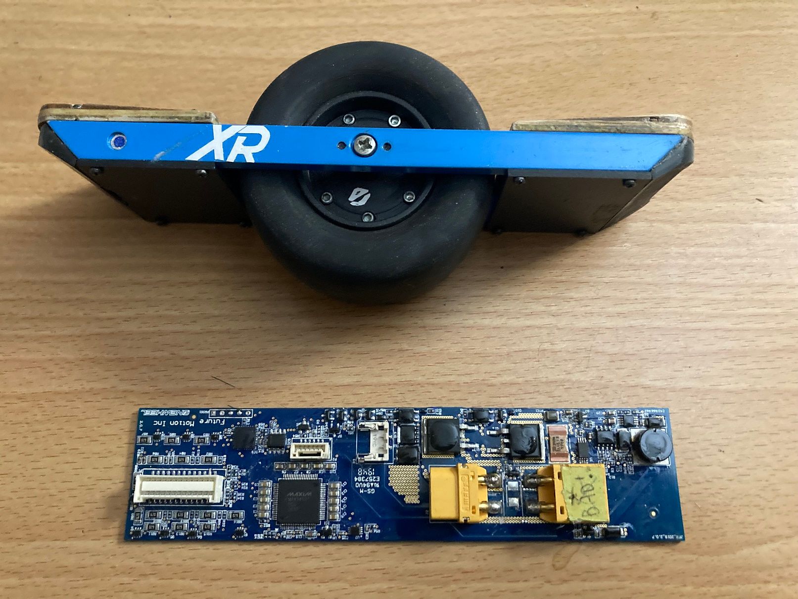
@s-leon Here's the scale model I built, I thought I posted it on the old site years ago.
I looked at an old picture of this model and the timestamp was July 2019, time goes by fast! First picture was 2019 and second picture is today. I had planned to put led lights in, but I lost interest.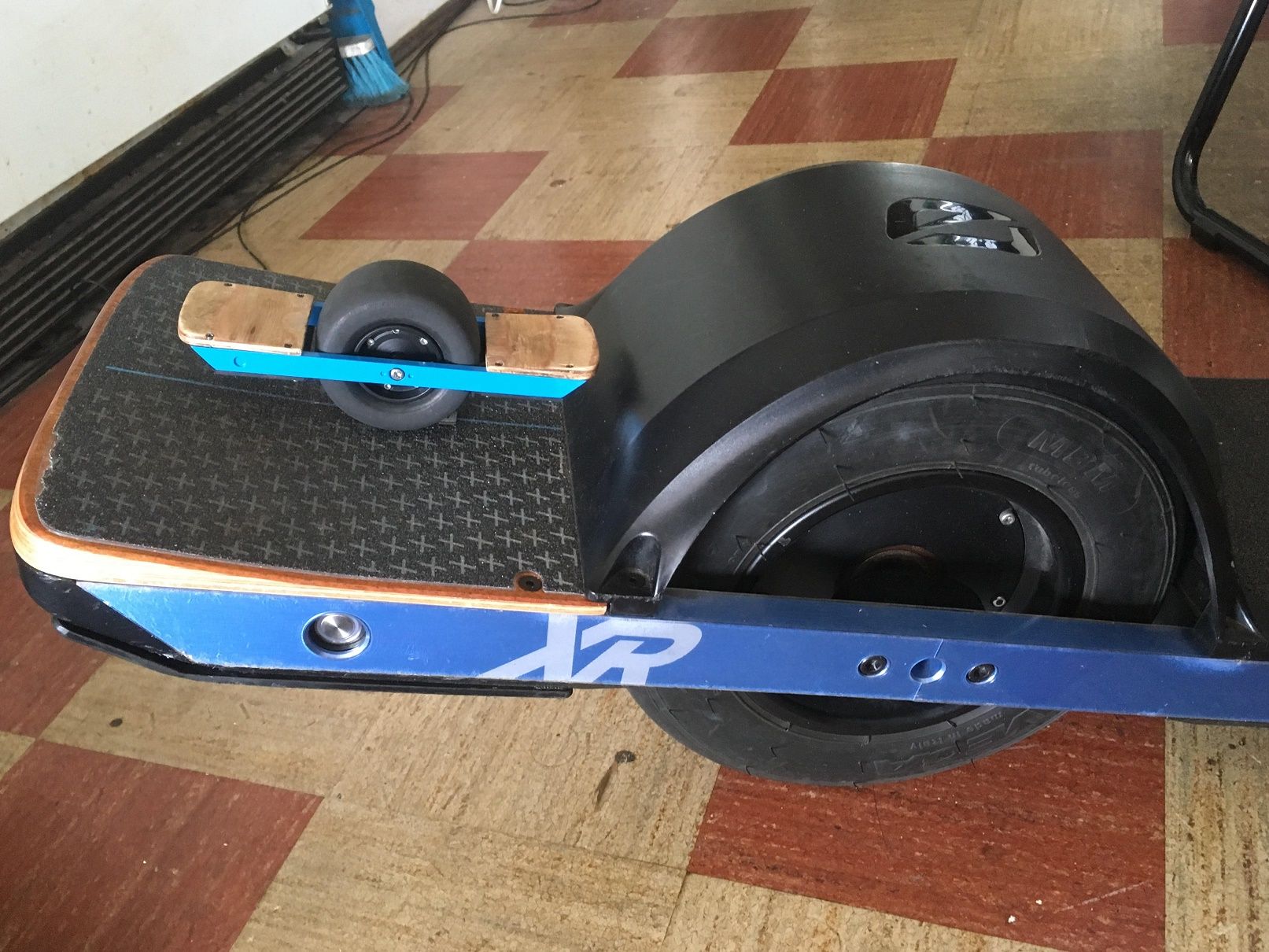
-
@lemur -- Very cute! ...And smaller than I imagined!