Extra LEDs For the Onewheel (Because RGB adds a 15% preformance boost)
-
@cheppy44 I actually have one lying around
So i tested it in tinkercad since I don't have any resistors IRL. It works with the pulldown, but only button 2 seems to be detected currently.
Also, I had to change the code up for the LED so that strip 1 is for the left, and strip 2 is for the right since I'm going to be placing them under the fender for now
Updated code:
#define PIN1        3 //Pin for Front Strip
#define PIN2        2  // Pin for Rear Strip
#define BUTTON_PIN1 4   // Pin for Button 1
#define BUTTON_PIN2 5  // Pin for Button 2
#define NUMPIXELS   4   // Number of Neopixels in each strip

Adafruit_NeoPixel strip1(NUMPIXELS, PIN1, NEO_GRB + NEO_KHZ800); //Setup for Strip1
Adafruit_NeoPixel strip2(NUMPIXELS, PIN2, NEO_GRB + NEO_KHZ800); //Setup for Strip1

int buttonState1 = 0;  // variable for reading the pushbutton status
int buttonState2 = 0;  // variable for reading the pushbutton status

uint32_t white = strip1.Color(255, 255, 255); //Defines a color later to be used in strip1.fill (r,g,b)
uint32_t red = strip1.Color(255, 0, 0);
uint32_t yellow = strip1.Color(255, 255, 0);

void setup() {

  pinMode(BUTTON_PIN1, INPUT_PULLUP);  // Pin for button 1 other side connected to ground
  pinMode(BUTTON_PIN2, INPUT_PULLUP); // Pin for button 2 other side connected to ground

  strip1.begin(); // INITIALIZE NeoPixel strip1 object (REQUIRED)
  strip1.setBrightness(4); // a value from 0 to 255
  strip1.show(); // Initialize all pixels to 'off'

  strip2.begin(); // INITIALIZE NeoPixel strip2 object (REQUIRED)
  strip2.setBrightness(4); // a value from 0 to 255
  strip2.show(); // Initialize all pixels to 'off'

  Serial.begin(9600); //start Serial console for debuging
  Serial.println("begin");
}

void loop() {
  buttonState1 = digitalRead(BUTTON_PIN1);
  buttonState2 = digitalRead(BUTTON_PIN2);

  // check if the pushbutton is pressed. If it is, the buttonState is HIGH:
  if (buttonState1 == LOW) {
    // turn left turn signal on
    Serial.println("button one left");
    strip1.fill(white, 0, 4); //strip.fill(color, first led index, number of leds to fill);
    strip1.fill(yellow, 5, 4);
    strip1.show();
    strip2.fill(red, 0, 4);
    strip2.show();
    delay(500); //delay for 500 milliseconds or .5 seconds

    strip1.fill(white, 0, 3);
    strip1.show();
    strip2.fill(red, 0, 3);
    strip2.show();
    delay(500);

  } if (buttonState2 == LOW) {
    // turn right turn signal on
    Serial.println("button two right");
    strip2.fill(yellow, 0, 4);
    //strip1.fill(white, 5, 4);
    strip2.show();
    //strip2.fill(yellow, 0, 4);
    strip1.fill(red, 0, 4);
    strip1.show();
    delay(500);

    strip2.fill(white, 0, 4);
    strip2.show();
    strip1.fill(red, 0, 4);
    strip1.show();
    delay(500);

  } else {
    // turn leds back to "normal"
    //Serial.println("normal");
    strip1.fill(white, 0, 4);
    strip1.fill(white, 5, 4);
    strip1.show();
    strip2.fill(red, 0, 4);
    strip2.fill(red, 5, 4);
    strip2.show();

  }
delay(50);
}
Update:
Checked the serial output and it does detect the button press, but nothing is changing with the LEDsupdate update:
Code works! :) Copied code from the rigth blinker and copied it into the if statement for the left blinker and changed strip1 to strip2 and vice-versaiam smort
Fighting the pavement since I started this hobby!
-
@loaffette sweet! the strip.fill commands are pretty useful when you know how to use them.
-
@cheppy44 yep!
Tomorrow I'll order the arduinos, some resistors and I'll add them on later on this week.
Need to focus on studying for two exams this week, but also I'd like to do a lot of my Onewheel work when I get everything for the Onewheel in! (This, life savers and the Badgersense!)Fighting the pavement since I started this hobby!
-
@loaffette did you decide which controller you are going to buy? For the application I do thing that any of the name brand arduinos may be a bit big.
-
@cheppy44 going for the Nano due to its compact size and okay price, though that's what I'm going to be using for now. Later i might switch it up to something else
-
Update!
The Nano(s) are ordered and will be here next Tuesday! I will begin working on making a mount for the arduino and the battery. I will make a test mount for the battery and I'll probably modify an already existing nano mount for now
-
Arduino Nanos have arrived!
Won't be able to do any work on them until tomorrow. Got slammed with two exams yesterday and today I've got classes until 5 PM then two homework assignmentsTomorrow, I will work on the arduino and I'll post the results
-
UPDATE!
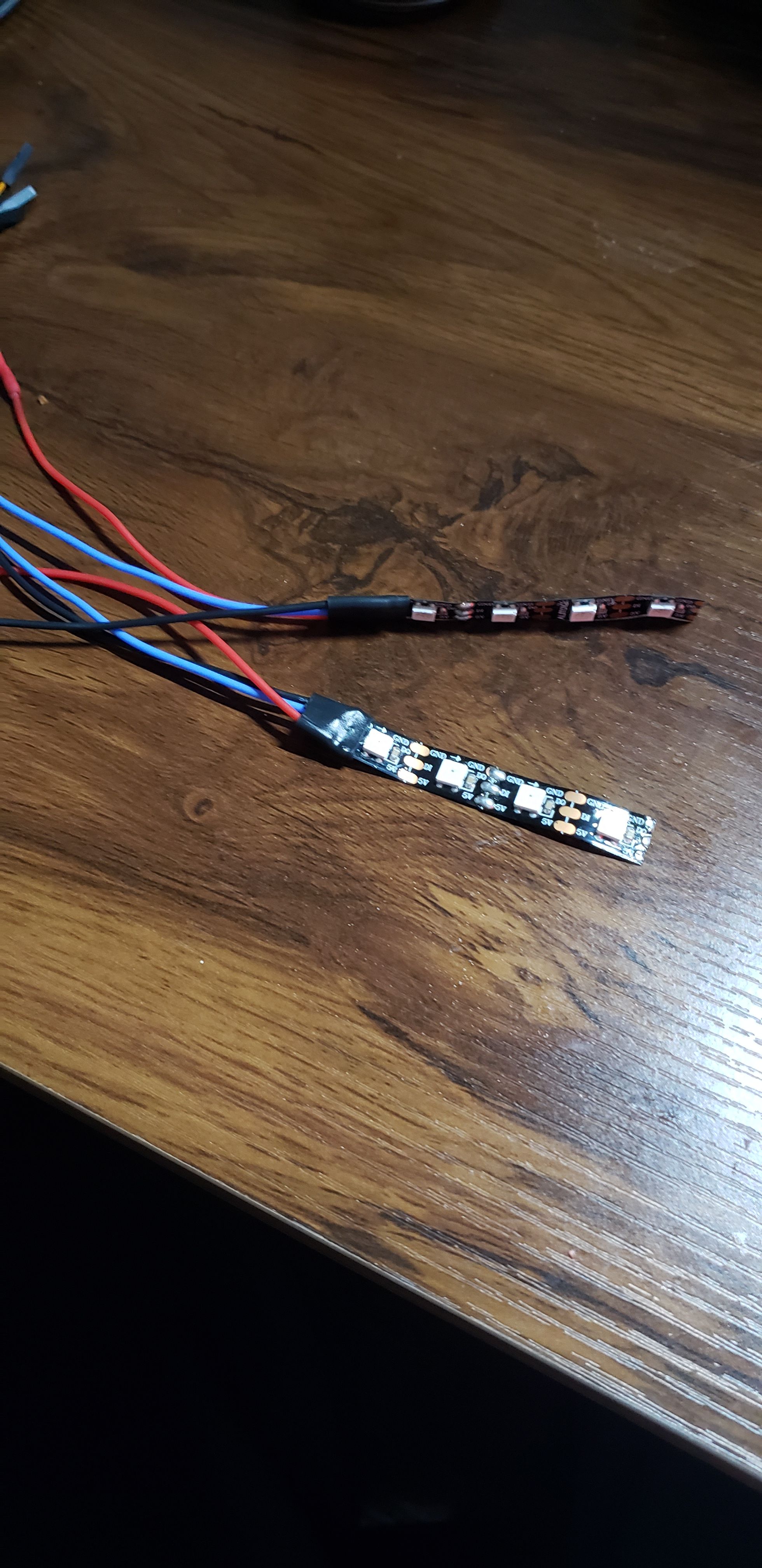
Everything is soldered together, but we have a few problems, mostly on my end.
1: Soldering job is horrible and I need to find a better way to connect the wires to the strips and I need actual wire that would be good for soldering. I have wires constantly coming off and I have to solder them back on, so I will have to go and find a way to solder those better..The LED strip I have are old and a lot of them are broken, and I also don't ahve any resistors.
But the code works with my arduino, I just need some better wiring and better soldering

Fighting the pavement since I started this hobby!
-
@loaffette Looking good so far!
-
@loaffette lookin great!
-
the battery came off of it's mount after a jump off a curb and the LED wires snapped off 5 minutes into a ride
I am going to do research into how to do wiring better lol
Fighting the pavement since I started this hobby!
-
@loaffette excellent job so far… 👍
We can see what FM would have gone through in board development early on eh?
I think now you have a working setup, hot glue and something like epoxy resin? would be good to set everything in place. A little permanent but would help I think… ???Edit…Heat shrink too
-
@puzz360 Yeah, that's the plan
I haven't soldered in MONTHS since the school bans anything that generates heat except for the 3D printer I've got in my room. (It's in an enclosure and the school knows about it, and doesn't entire care as long as I don't blow a fuse). My soldering isn't as good as it used to be and I struggled to make good connections on the solder pads and ended up having half of them ripped up. I'll have to order more LEDs and some solid-core wire, though I have an idea. I need to find a 3D scan or model of the fender I have and then design a clip or shell that will go on the edge or buttom of the fender.
I'll be working on 3D printing and designing some test parts for S-Leon's light bar for the badgersense so I'll just throw this project into it as well.
I'll make the CAD files public when they are finalized!
I'll also try and work on an actual enclosure that fits the curve of my current fender as a start.
Since I know the concept can work now, I'll just have to start refining it
-
Ok, update:
I've had a lot of stuff happening, and I'm trying to deal with it RN. I'm fine, just a little...
tiredThis weekend I hope to make the first working and functioning prototype for my RGB headlight project. Found some resistors, buttons and a spare LED strip to use. I also got some actual wire for soldering, and I do plan on 3D printing out cable reliefs for the LED strip connections.
I will post those models publicly when they are tested and ready
-
Soldered the LED strips up today, and was gonna connect them to the arduino nano, until I realized that there is only one 5v rail on the Nano. Might either run a long wire from the 5V out on one strip and to the other one, or splice two power wires into one..
-
Fighting the pavement since I started this hobby!
-
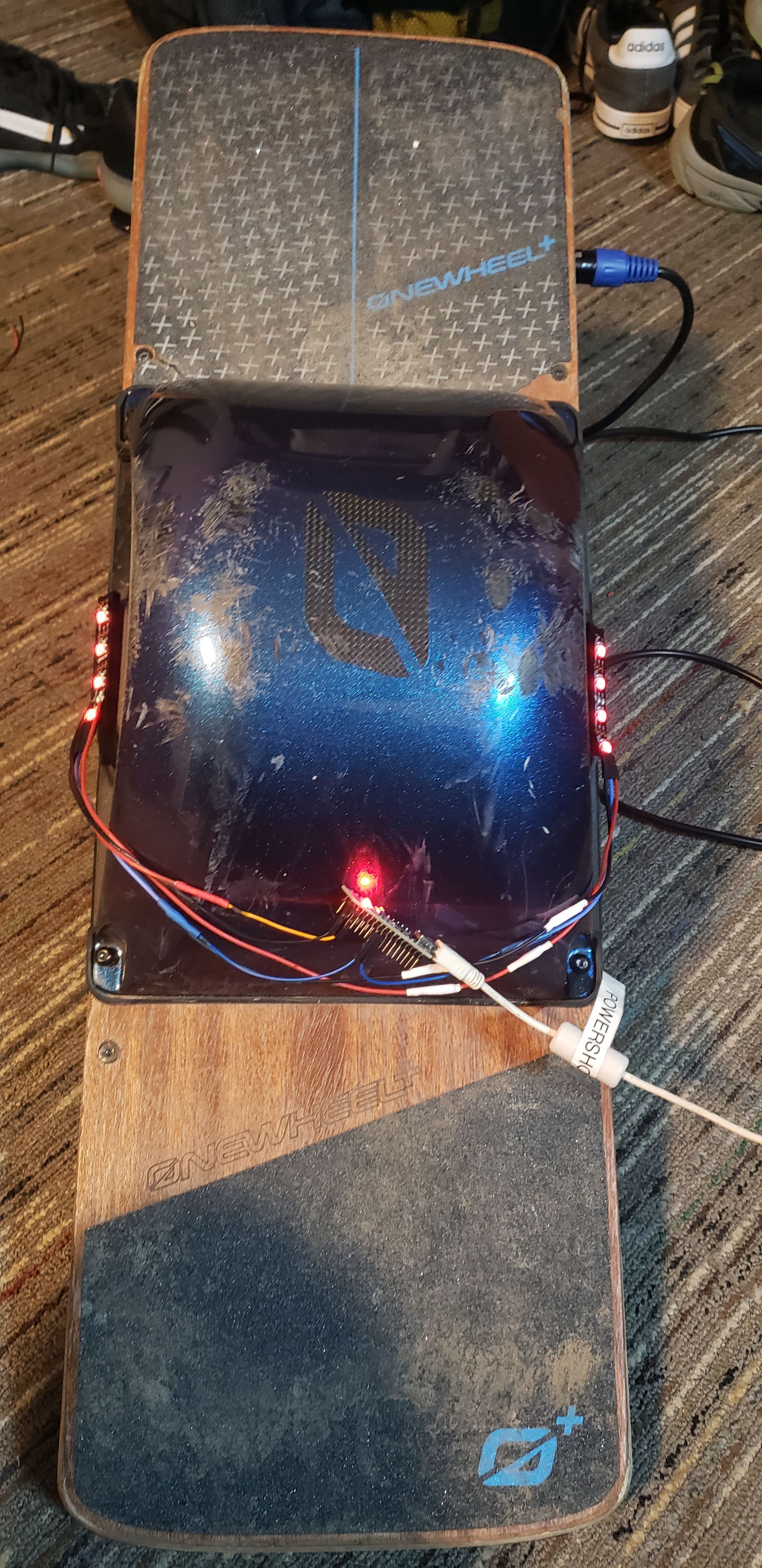
@loaffette Did a test ride last night!
Battery pack stayed on well during riding, and the lights stayed on. However, whenever I dropped off curbs, the battery just flew off. I think there needs to be a better system for connecting the battery to the system, maybe making a mount that matches the shape of the fender and uses double sided tape or a lot of command strips...
LEDs were nice, however they were not bright at all. Looking back at the code, I was unsure of how to make the LEDs brighter, and I am looking into trying to add a rainbow color mode to it. I'm trying to get the general system down before moving to making a wired remote. After I get the remote working, I will move to make a wireless remote.
also, a dumb idea but part of me want's to add IR LEDs so when someone takes a picture, they see ghost lights on the board >:D
Will need to talk with @cheppy44 about making the LEDs brighter through code. I know they can be brighter, but I'm unsure if it's my LEDs or something in the code..
Fighting the pavement since I started this hobby!
-
@LOAFFETTE said :
...
also, a dumb idea but part of me want's to add IR LEDs so when someone takes a picture, they see ghost lights on the board >:D
...Tell us more about that part.
-- Priorly I've been guessing the wavelength of IR LEDs only affect equipment aiming you in night vision mode. Since ppl out there late at night or in low-light urban structures likely snap you with their smartphones either just with flash function or without. They likely don't get that glare on picture.
Or I'm missing smth? >some reading< -
@sirgu From what I remember, phone camera's in general are able to see IR light if they don't have a filter of some kind for it. Take a TV remote, point the front at your phone camera with the camera app open and hold down a button and look at it through the camera.
I'd need brighter IR LEDS or a lot of them, along with some testing but I do think that if I can get it to work, that it would be a cool effect.
Fighting the pavement since I started this hobby!
-
@LOAFFETTE You are correct! I tested it with my old-school Pioneer remote (the only IR thingy in my household) -- the phone does spot a tiny ~3mm purple dot out of that 0.7x5cm reddish plastic strip. But it's far from any glare.
Oh, I get it now ... could it be that our interpretation about "ghost lights" were likely two different worlds?
E.g. dotted hidden messages/figures on OW fender can be cool as well.
From my perspective, the top notch effect lies in bright glare covering the whole unit without ever leaving the chance to guess out of its silhouette what's on the picture under the persons feet. For that purpose .. without the assistance of any night vision mode .. those IR LEDs better be darn powerful!