Vesc Conversion Status (Rose/Mika)
-
Hello!
I'm back with another update!I've decided to start on a project to make a CAD replica of my board just so I can easily reference where everything is and better plan out mods and upgrades in the future.
To add to this, I've also run into a slight problem
My battery is cooked.Ok, let me be less dramatic. The board still powers on, it still runs and it still goes over 20 mph, but it's range is abysmal. After 3-4 miles of riding, the board is left at around 50-60 percent capacity. It's top speed has also significantly dropped over the past month or so, going from a top speed of 23 down to 21 at 80 percent duty cycle.
I checked my odometer, and it is right now at around 2960 miles. (Adding in the odometer reading from the stock XR controller and onto the current VESCs odometer, which is 2500 miles off)
That's... a lot for one year of owning the board. I'm proud that I've used something that much, but it's left me stressed with how much longer it'll last. I'm hoping to make it to winter break and to Christmas so I can buy a new battery, BMS and charger but with the cost of all of that, I'm uncertain
For now, I won't ride the board too much or be excessive with it. I'm going to try and make sure I don't do anything too crazy and I'm going to keep an eye on how the battery is doing. I may try to do an OWIE mod for the BMS, just need to find the time to do it
In other news, the board hasn't had any major breakdowns of any kind! Nothing has melted, broken or snapped off! That is good for me, since it means I have less to worry about.
-
Back again!
Started on a project to make a 1-to-1 CAD model of my board. I am working on the axle blocks and the rails currently. I think I'm pretty close to being on point with the thunder rails, but I need to get the insides right
Here's what I got so far:
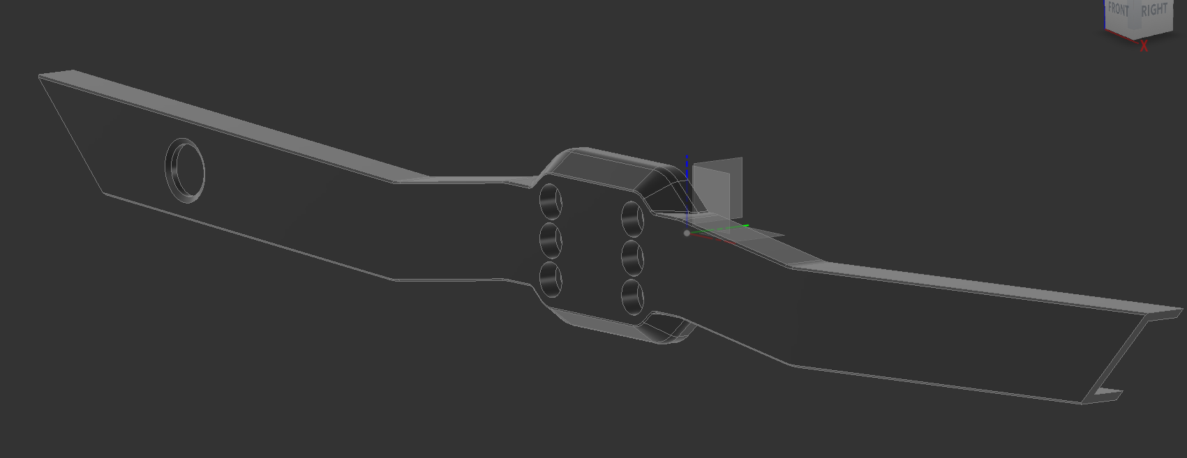
The axle blocks are missing the chamfer on the other side, I'm struggling to replicate itI will not be posting the thunder rail .f3d file since I don't want to get in trouble with Fungineers, and it would be a little mean
-
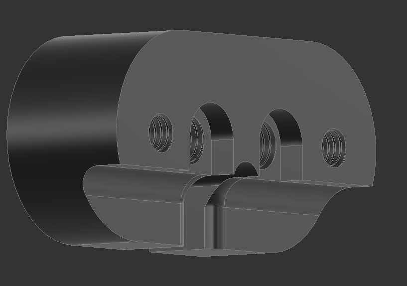
Also, in addition, I made this:
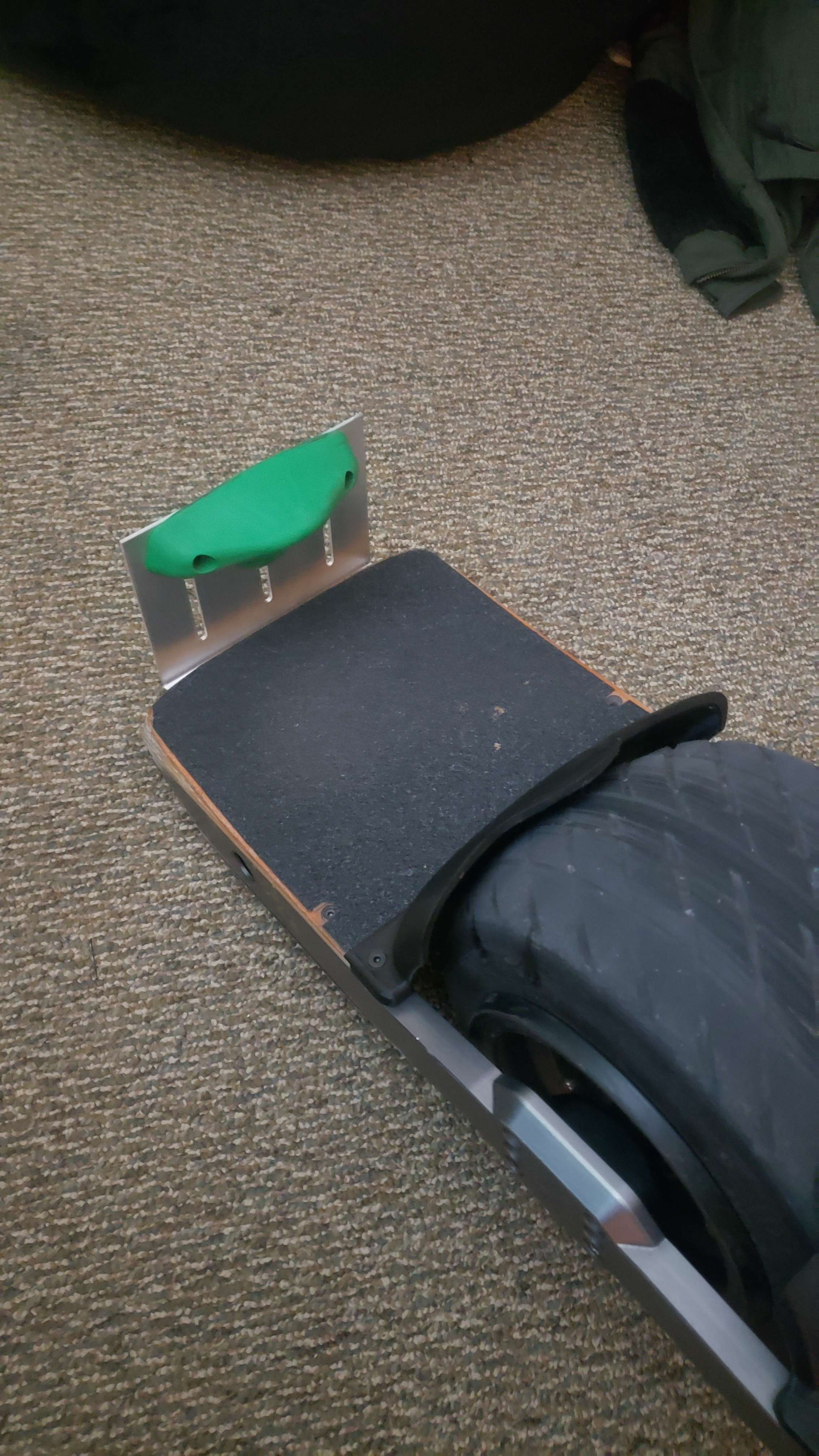
I got sick of the mounting solution for the flight fins, so I made this
You can mount it under the bumper, or in between the footpad and bumper.
I will refine the edges to make it less sharp, but once I do and I confirm it works, I'll post the .f3d file
used sendcutsend -
Guess who's back!
so my parents bought me a 18S2P battery from the BoardGarage that runs off of 50s cells. They also got my an accompanying charger and thr XLITE-V3.Spent all day setting it up, and it works!... after I accidentally plugged it into the stock harnesses reverse polarized connector. Had to replace the XT-60 on both the battery and the harness
gonna rip her around the neighborhood this morning, I'm excited
-
this is the board about twelve hours ago
-
The Ubox 80V died
Ordered a replacement ubox 100V from avaspark
I would have been cool with this if this was a week or two ago, but it being now with four days before college really stressed me outFighting the pavement since I started this hobby!
-
@loaffette Oh no how’d it die? :(
-
@lia absolutely no clue
Battery reads a good voltage though, and the Ubox light doesnt turn on, even when plugged into USB
my guess is that some of the thermal paste I used to thermally conduct heat from the ubox to the lid somehow got inside the controller and shorted itI'm hoping to have it in by wensday so I can get it fixed before school starts
Fighting the pavement since I started this hobby!
-
@lia so I took some time and I cracked open the Ubox
Found out that a tiny surface mount capacitor/diode/resister thing poppedI also was running it on 45A field weakening so that might have done it out
-
Ladies, Gentlemen and everyone in between...
We're back
I got my Ubox 100V in. Had to swap it into a 3D printed box. I used 3D printed cylinders as inserts so the screws had something to screw into. The lights don't work and I need to work on modifying a flowglider box to add a headlight pannel.
Motor has some weird crunch, and I'm still working it out
Also, the Ubox 100v is held in using command strips. It works, I'm not gonna complain about it lol
Board kicks like a mule, and apart from water-proofing it and printing out a new controller box using PETG-CF, and a new tire, this thing is basically as close to finished as it will be for a while -
So I wanted higher-desnity LED strips, but I didn't want to spend money.
I did have an LED strip through, so I commited a crime against electronics
It's LED strips cut, then soldered with a bend in it.

I feel like a genius but at the same time I feel scared that I haven't seen something that I should've seen
-
Umm, .. that's a lot of vibration these solder joints must withstand. Thought of some epoxy backing or smth? I have no idea how much room you got there to play around.
-
@sirgu thats the plan
-
I'm back, and I have some news about the board.
The housing that holds the controller is also breaking, as it was printed with PLA that I had lying around.
Another issue is that the motor was acting up, making a “chugging” noise and motion with each rotation. Essentially, at low speeds the motor would drip the nose suddenly before catching the nose and raising it back up. This can be caused by a broken sensor in the motor or a broken cable in the controller.
First we need to print off the new controller box to replace the damaged controller box. As pictured below, the box has a split running across the ports, which could spread and cause the
entire controller box to split and separate while riding, which is not ideal.
I managed to buy some PETG Carbon Fibre filament which should hold up to the abuse this board will inevitably see and make it look less visually offensive. (I mean, rainbows are cool and all but I don’t know if that is the color scheme I want to run with.)

As pictured above, this is the new box that was 3D printed. I am genuinely impressed with the quality of the print. The printer I’m using is a Creality Cr-10 Smart with the hot-end swapped and running direct drive. I would not recommend the Cr-10 Smart, as it has… problems…
While that prints, we should prepare the cable. First we need to add the proper connector that will feed the battery power to the controller, which is a beefy XT-90. I should invest in some soldering flux, but I will wait until I have a proper work table and not an apartment bedroom and kitchen.


We will use heat shrink to cover the soldered connections to prevent shorting.
On the battery end, we will use some dunpout connectors to create a connector for the back headlights. It took some trial and error, but I finally got the hang of using cheap crimpers!
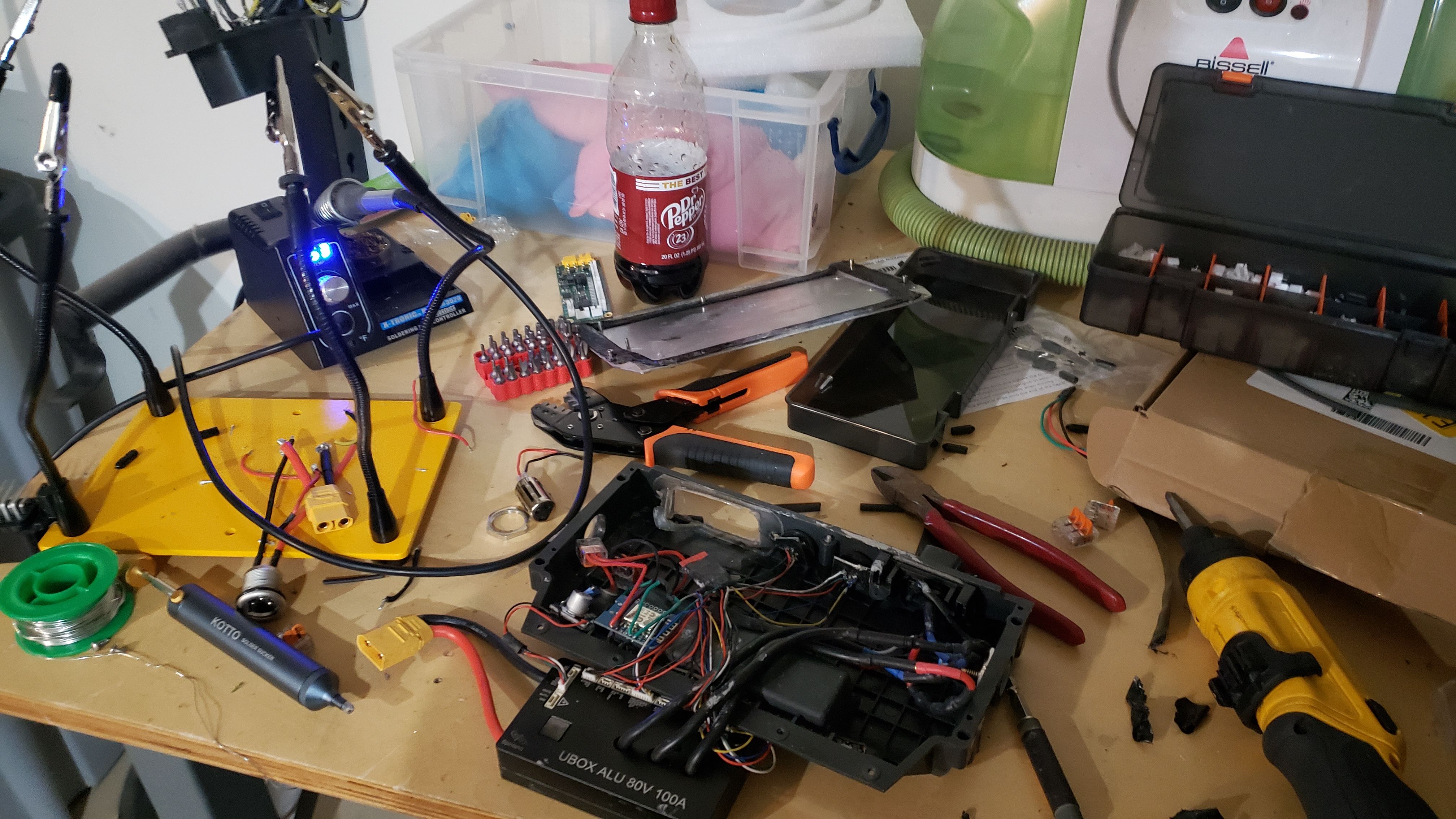
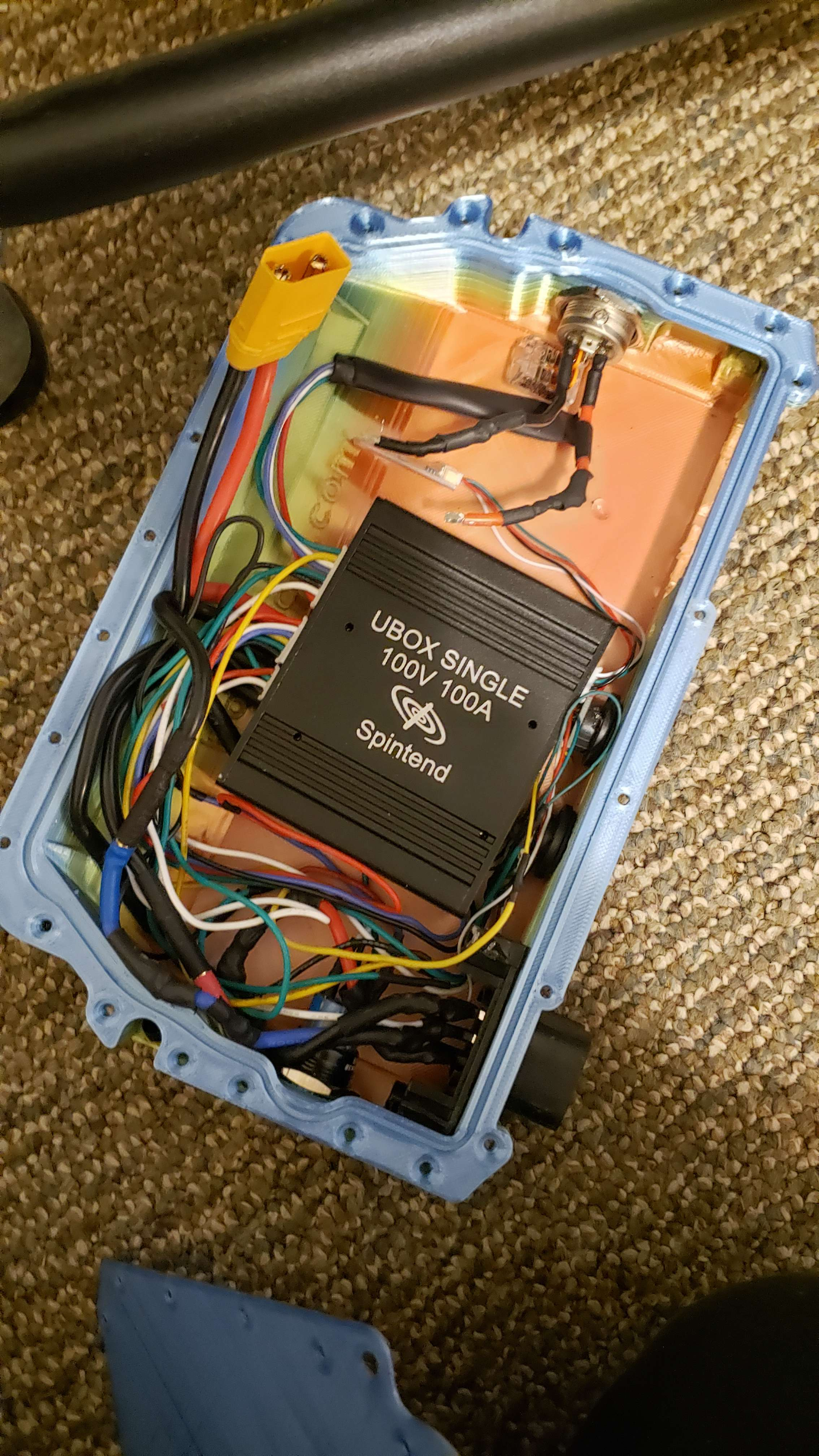
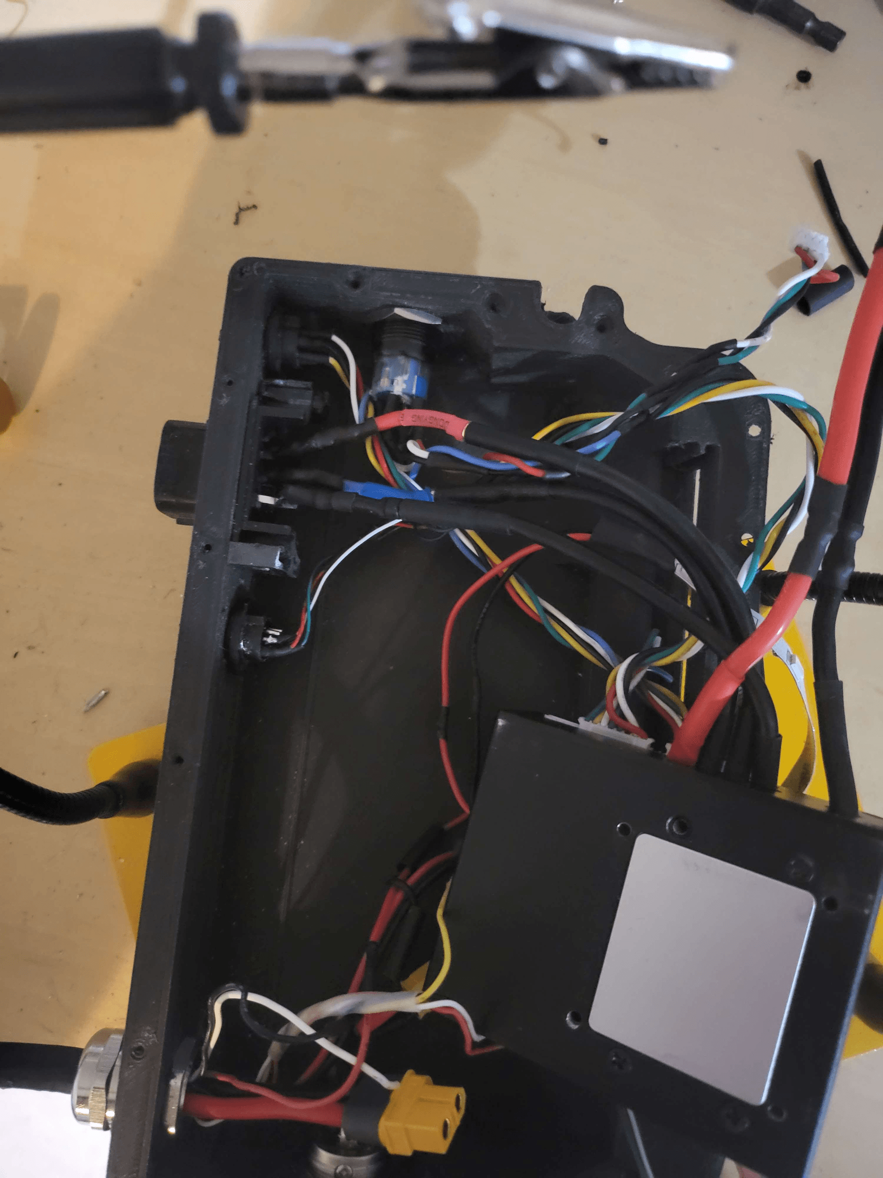
After that, we can finally get inside the controller box and take a look inside! It’s a rats nest, but I currently don’t have the time to properly measure out and plan a routing path for each wire. I may try and look into getting custom-made PCBs in order to clean up the wiring or at least make it look a little nicer, who knows.

The controller in the center is held in with pressure from the lid and two of those command strips.
I have no regrets for the jank.The old automotive Molex connector was removed, and after +3000 miles of use, it can finally be retired. This was pulled off of the original XR controller board, along with the motor connectors and the footpad connector.

Moving the charge plug from the old controller box into the new carbon fiber one, we can get a better idea of what kind of mess I’ll be dealing with. I should also mention that I had a cable made, along with an adaptor plate cut from a plate of aluminum. It adapts a cable gland to the Molex connector provided by a community member (thanks Pickles!) The cable gland should better seal the cable to keep the water from leaking in while riding through water. The controller box I printed out was modified to fit the acrylic headlight panel from a stock XR box, along with making some extra space inside. (I also tried to remove the flow glider logo since on the previous box it caused some issues with the Ubox and the wiring, but I failed to remove all of them. Don’t worry, I won’t be uploading the CAD model with the text removed. When I upload it, the flowglider logo will be back on there!)


The headlight panel is held in with superglue and a lot of flowable silicone.
At this point of the project, every surface of my room has turned into a workspace. I’m currently using my bed with a bunch of paper towels to work on the controller box.With some rewiring and some continuity testing using my multimeter, I figured out that one of the sensor wires came loose on the motor hall connector. It is not pictured, but I re-wired the connector to make sure this never happened again.

After double checking my wiring and making sure I didn’t break anything, I sealed up the controller box. I measured the circumference of the board, and divided it by π to get the diameter since the tire has seen some significant wear since I last got an accurate tire measurement and the air pressure inside the tire changed, and I forgot what tire pressure I used.

I also added threaded insets so the box could be screwed into using my soldering iron.

Also, a careful look at the picture above and you may notice a 4-pin JST connector. This is planned to be used so I can use external LED attachments without having to use their own batteries. This should let me make a LED fender that I hope to build at some point.
I unfortunately found out that I had to undo some of the lid screws as they intefered with the fitment on the rails of the board. I probably should invest in some counter-sink screws, but that’ll be for later.

The board has been problem free ever since, minus some slight motor crunch while breaking that I can't seem to fix. The board has a ton of kick to it, especially with the 18S battery built by @TheBoardGarage !
Fighting the pavement since I started this hobby!
-
@loaffette damn, I lost all of my images. I will look at trying to replace these
Fighting the pavement since I started this hobby!
-
@loaffette Oh no!
Feel free to just upload them here so they don't go walkies. I didn't know discord binned pictures or maybe they just changed the url for them.
-
Fixed a few of the images
Still looking to find the old ones, so we'll see
I also included new wiring diagrams for footpad and hall sensor
I hope it is adequate -
I'm back
I'm fixing my vesc. It's 1 AM, my VESC has been in pieces for about four days.
I've had to rewire and shorten the wires within the battery box, redo the LED strips because they broke, rewire the entire controller-side, remove the footpad and hall connectors from the PCBs, re-solder the controller's XT90 and swap it for an XT60, drill new holes for the controller box because the lid I bought didn't line up with the existing holes, and I've had to do all other thingsslight rant but..
If VESC is ever going to get farther than it is, someone needs to make a few things obvious or make sure everything fits. The last two controller boxes I've printed have had misaligned screw holes for the lid..I'm tired, I'm going to bed
-
-
Back again
Avaspark sent me an STL link for a controller box that should have had everything I needed.
However, it had a bump sticking out that I should have looked at more closelyI can't get the bumper on fully, so I have to re-print the box
Fighting the pavement since I started this hobby!