Trace Map Continued
-
This is insane. I've always just poked around boards with a multimeter and a lot of times, got nowhere. Didn't even occur to me X-ray is the way to figure this stuff out... and then to have some lunatic map it all out lol. Amazing.
-
@blkdout -- As a Navy aircraft mechanic in the South Pacific in World War II, my dad told me that they would x-ray the engine parts to be sure there were no cracks in the metal. This tracing of Onewheel printed board circuits seems much more sophisticated.
-
-
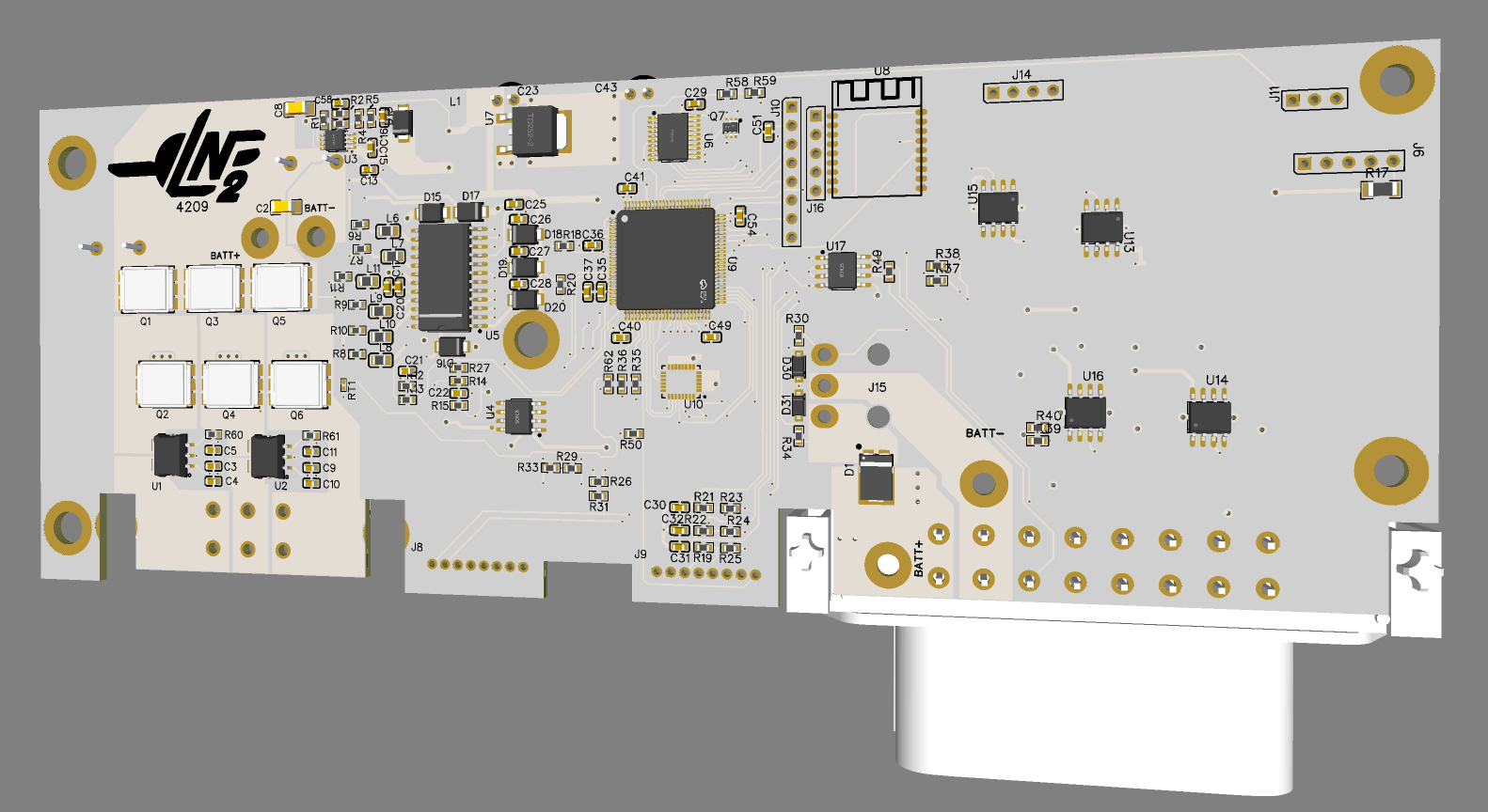
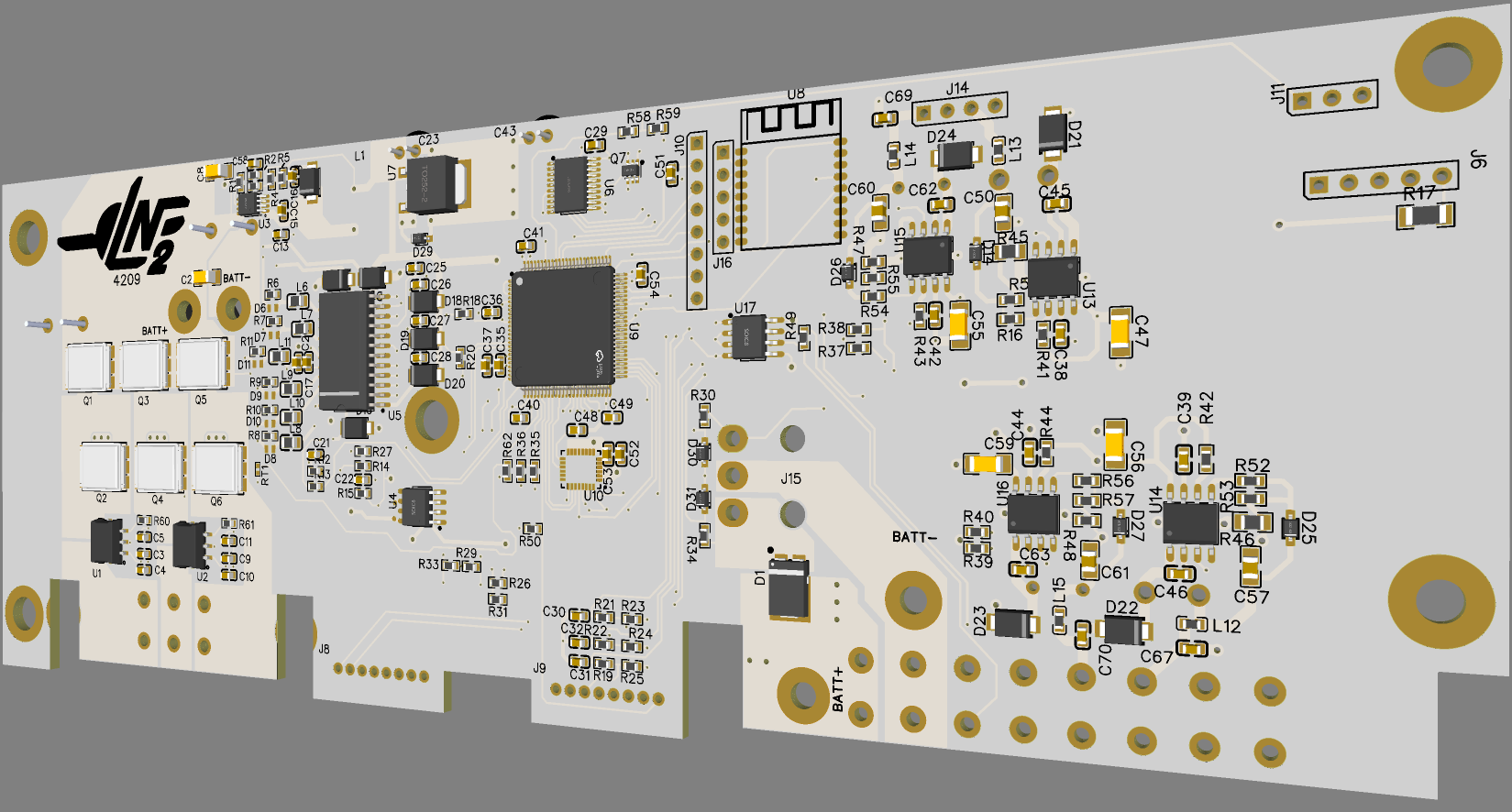
Finished mapping the traces (I think. I don't see anything I've missed yet)
Still need to tidy up the schematic and find the values for a bunch of components too. The inductors and diodes will not be fun >.>
-
@lia said in Trace Map Continued:
Finished mapping the traces (I think. I don't see anything I've missed yet)
Still need to tidy up the schematic and find the values for a bunch of components too. The inductors and diodes will not be fun >.>
Is just impressive. If you could make it work, it would be the resurrection of dead XRs...
If you could beef it up (like doing a 18s-20s), and make it much better, then this would be the vesc killer... I would be your first customer
White looks amazing BTW... -
Put out some feelers to buy a busted controller I can use as a guinea pig. Don't really fancy using a working one unless it's 4210-13 in which case it will be a worthy sacrifice.
@ed_co One step at a time. I'd need to brush up on so much electrical engineering to have any shot at making it work.
Other than the mosfets and driver IC a few of the caps and the primary buck converter U3 would need upgrading to stay in a safe margin. I do have a GT sitting next to me that I could maybe reference
-
XR's got what plants crave!
-
@notsure Sorry ;~;
I figured since those ones need extra work to mod it's worth testing those. That and I'm interested in those fancy new connectors they added with the extra bracing since I wanna use those too but cannot find them. -
@lia Have you found a buster controller? I guess US is full of them... Here in Europe is a lost cause...
-
@ed_co There is one that I might be getting but we'll see, no promises on it though.
I'm over in MN and SF next month for a bit so not sure I'll see any work on it till after that at least. -
I have the donor PCB that @TheBoardGarage has graciously provided (thank you so much ^-^) and I'm back in jolly ol' England (I don't want to be here let me out). I've ordered the V1.1 prototype to start work transplanting the components to:
A - Validate my work
B - Give me a canvas to start making changesIf all goes well I'll do V1.X on a known working unit and then my own personal XR with the fancy new changes.
-
Waiting on V1.1 to show up I've already started sinking my lil kitty teeth into the Pint that Mario also sent me (Thank yooou :) ) and I'm already noticing some odd changes between Zagreus (my old resurrected pint) and the fresh one. The bluetooth module is raised on a PCB wafer... for some reason. I assume better isolation from the internal planes on the controller itself or just a bit more space off the chunky aluminium case.
Oddly both have "3.1.3" silked on the one side which I assumed was the revision but maybe not.
The mosfet driver is the same with just a change in the actual mosfets and presumably the passives surrounding it.
Makes me wonder if the GT uses the same one too... in which case upgrading the power of these things might be a case of beefing the mosfets alone then just poking the firmware so it knows how many tins of Heinz it can give.
-
-
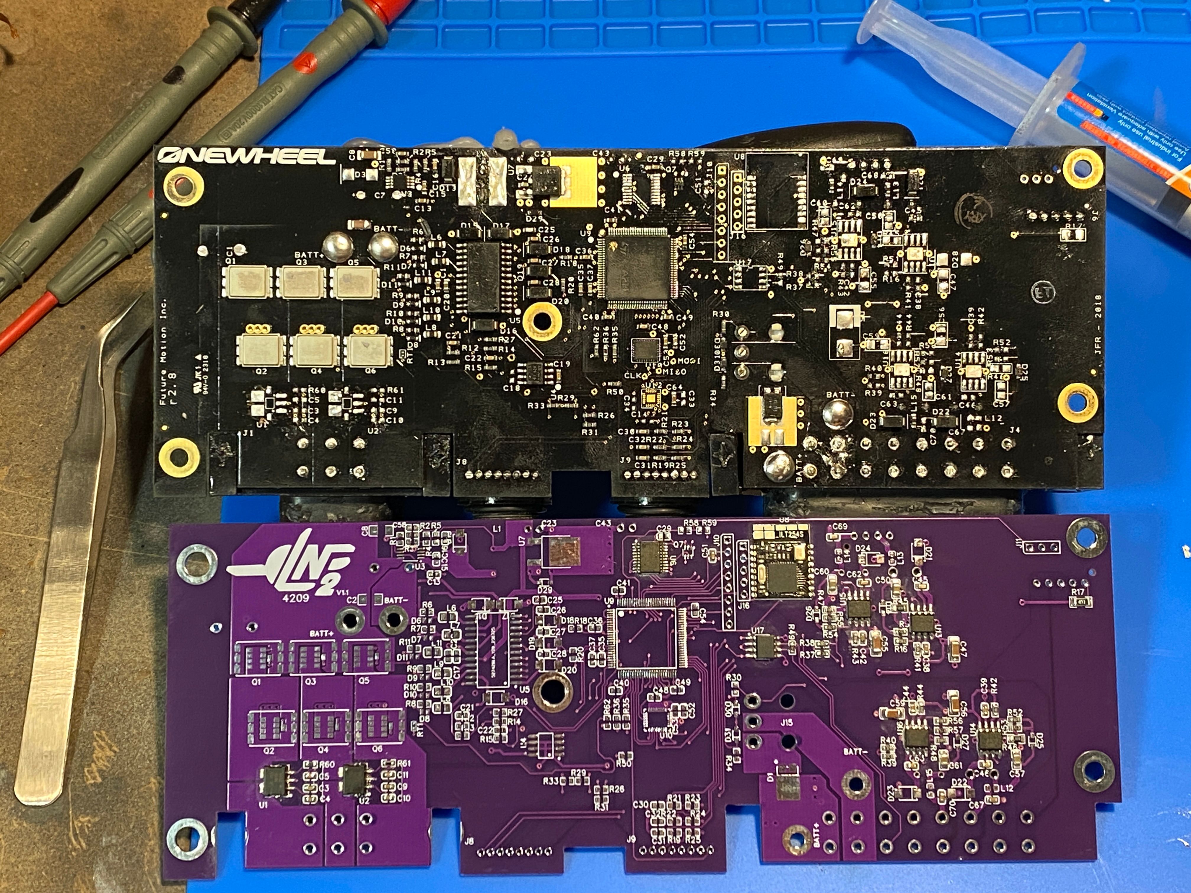
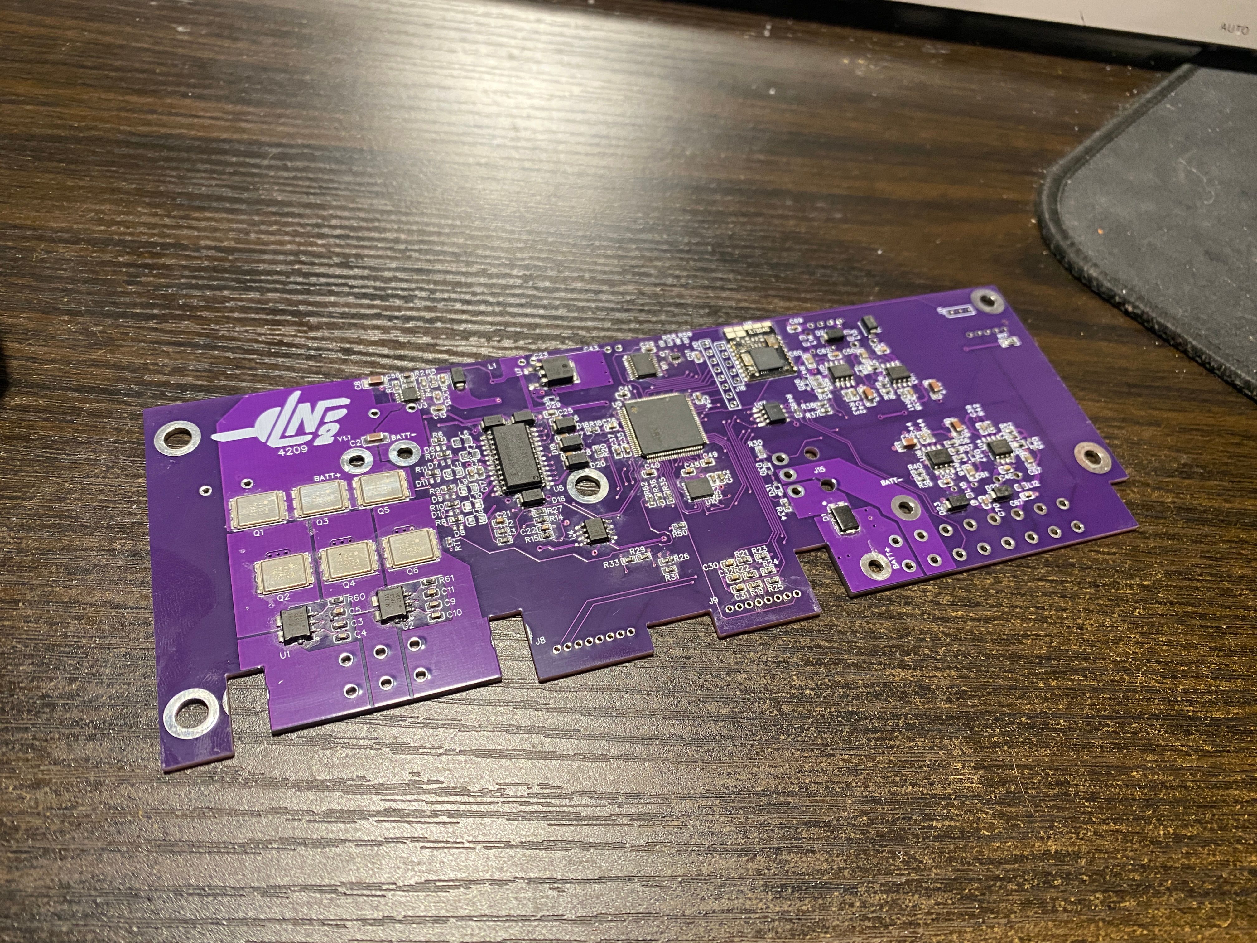
I'm gonna be a busy girl this weekend (The LEDs came too)
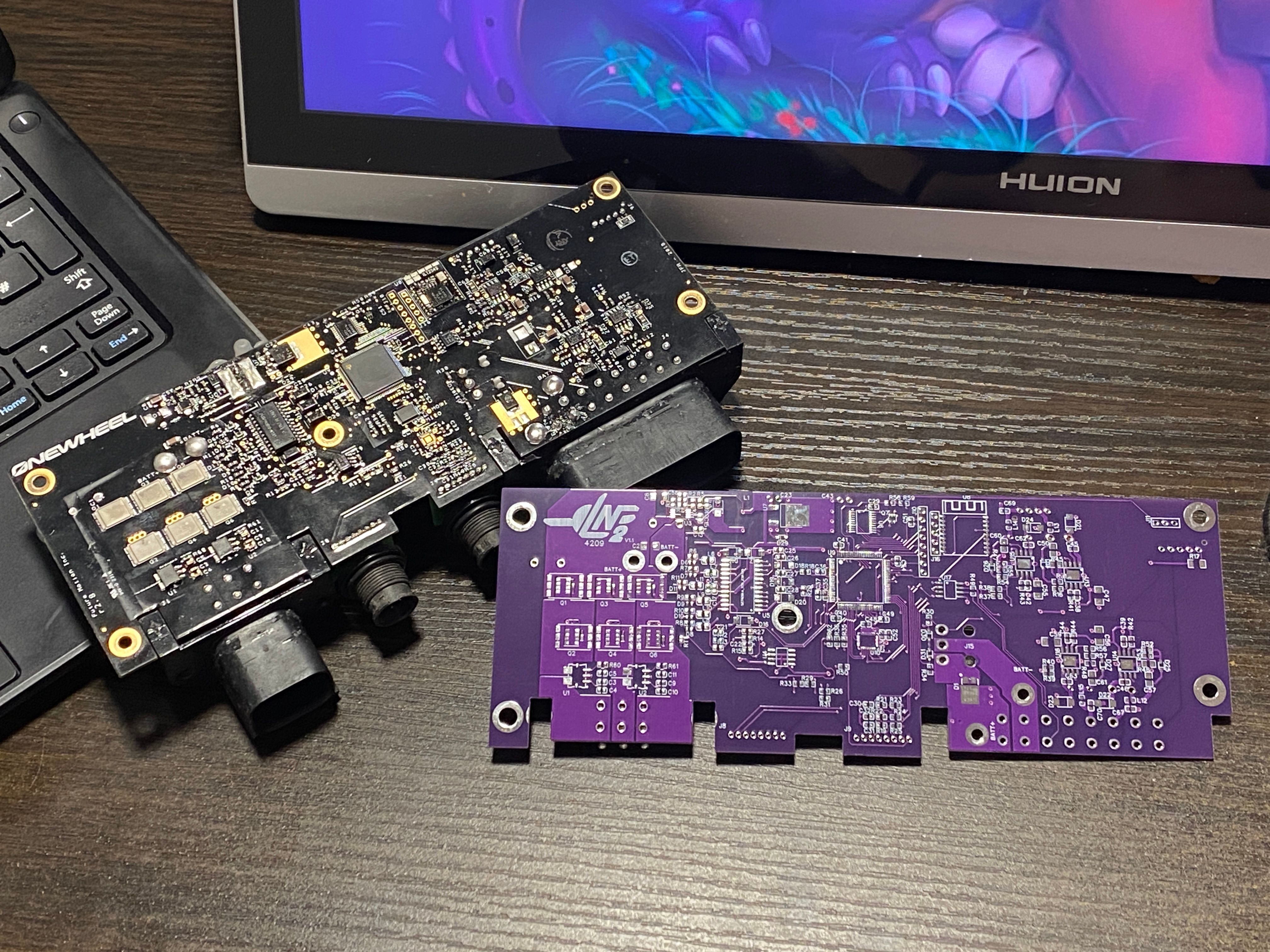
Did this in purple because white is like 2x for some reason. Didn't want to do black since I might mix them up lol.
It's going to take a while doing the transplant since I'll be measuring each of the passives between desoldering and re-attaching so I can fill in the schematic and get the next revision done as PCBA.
-
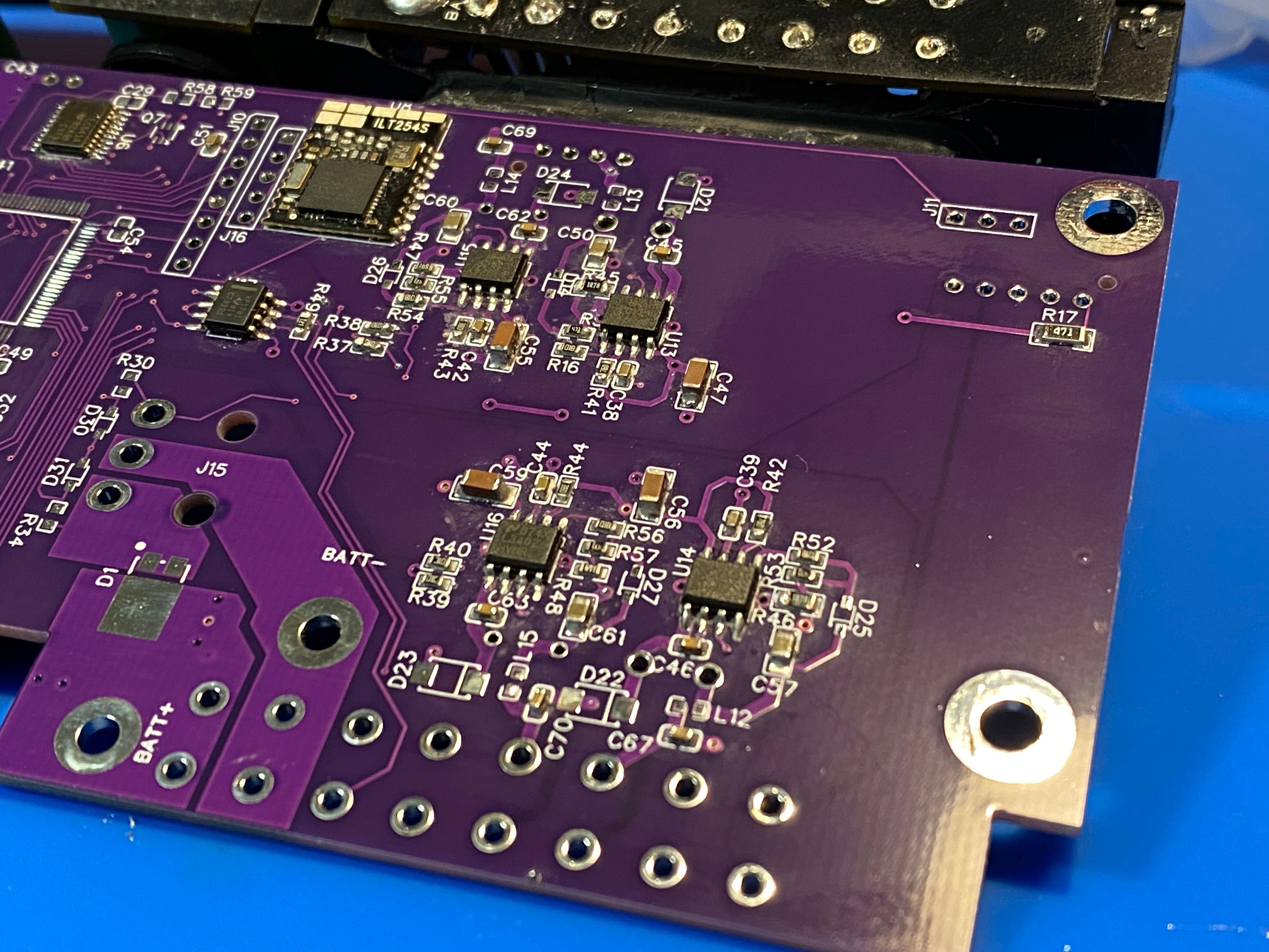
Progress is slow. I realise I missed C68 which appears to be some sort of filter cap on the front LED side. Oh well. I've measured all the components I swapped and with Nick's help of writing them down as I read them (sped things up a lot) I've got most of the LED side and the current sensing part of the ESC side done ^-^
-
@lia great work indeed.
Is that the 4 holes by c68 for the LED riser ?Just thinking in advance for trouble shooting my dodgy LEDs ;)
-
@puzz360 It’ll all stock on v1.1 however v1.2 will put the led segments on modules on the reverse. The idea being I want to replace the leds for addressable so a modular approach means choice and an ability to only do a single side ^-^
I’m taking measurements so if you want to pass values of suspected bad parts by me let me know :)
-
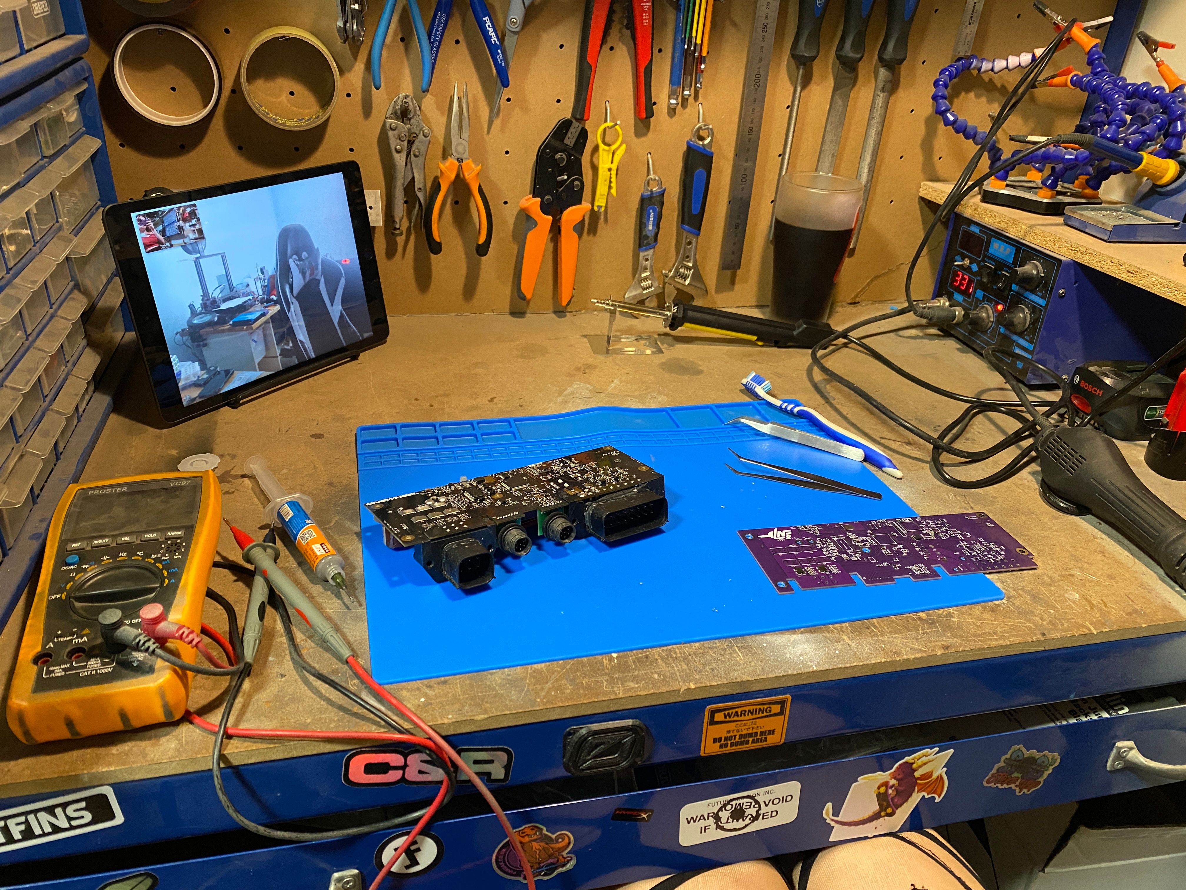
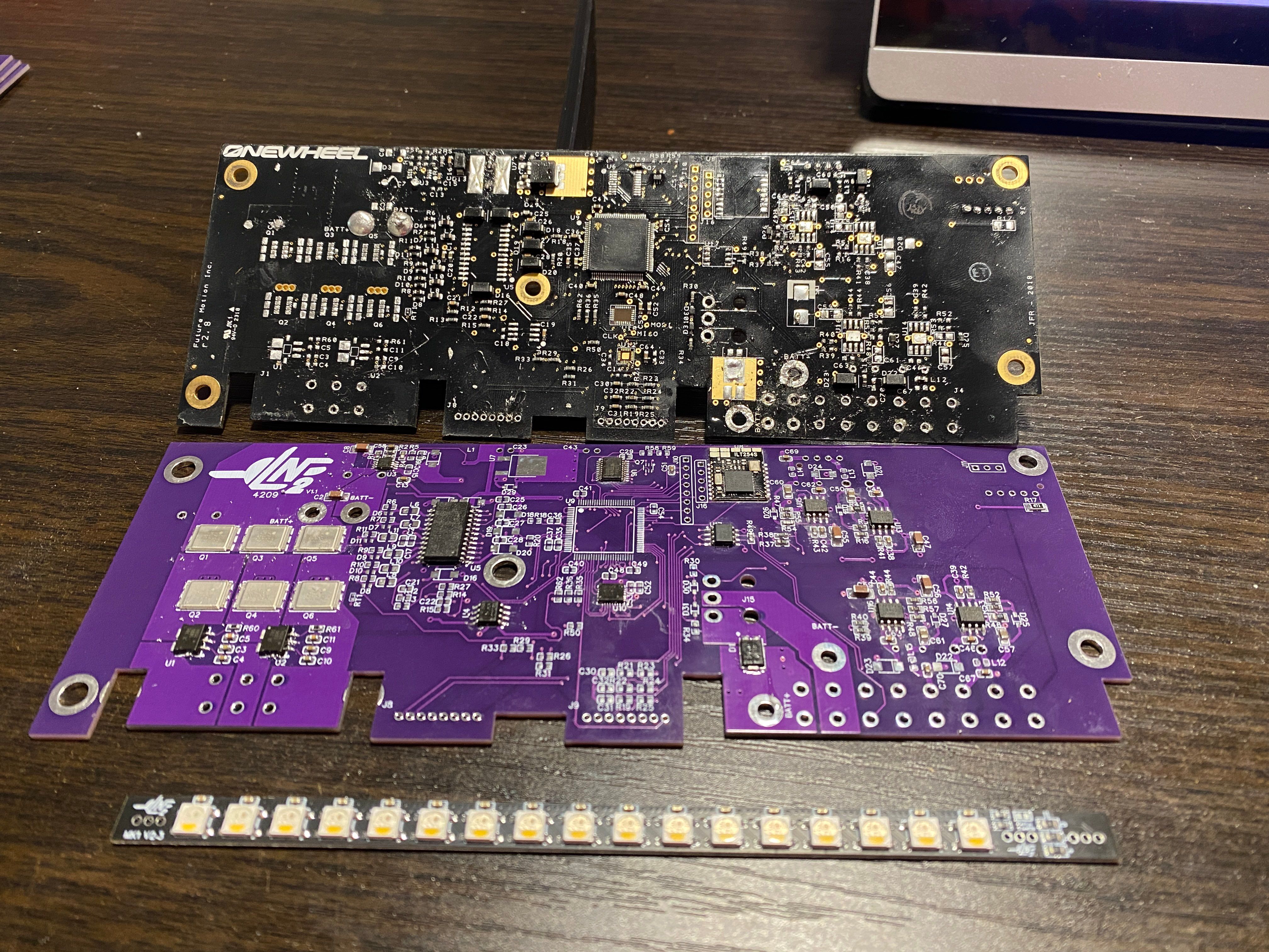
Painfully slow but more is off, a lot of the chunky connectors and components on the large voltage planes.
-
Was sweating bullets with this step...
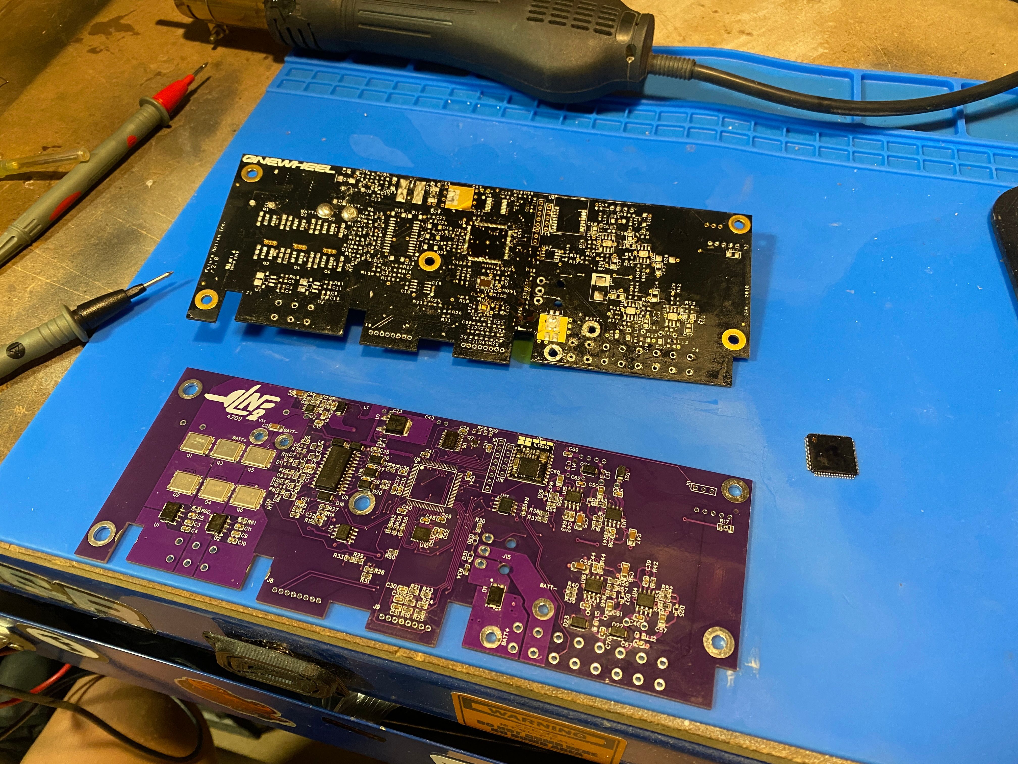
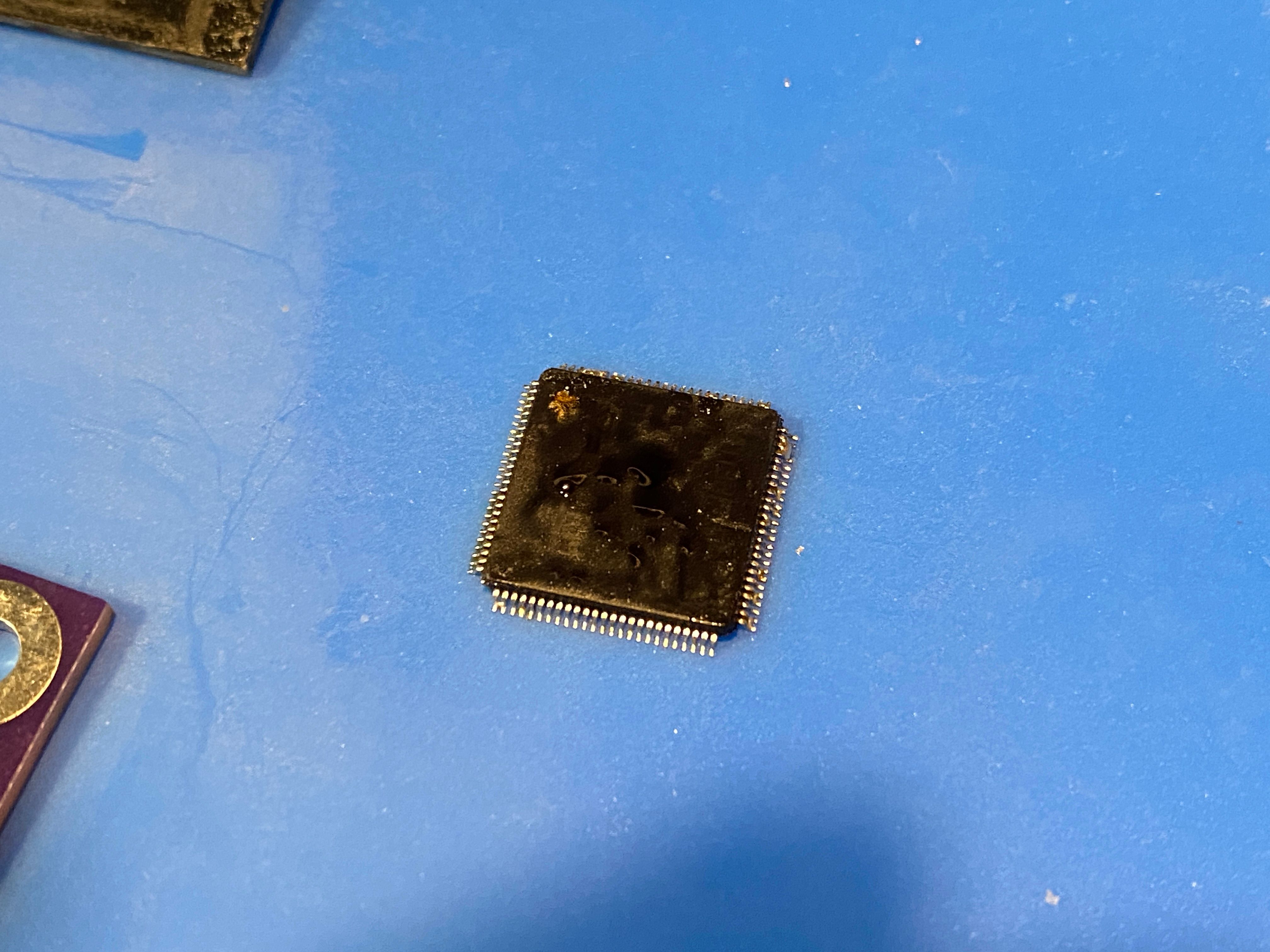
So far it looks happy from some "kinda sorta not really" scientific measurements to validate no massive mistakes. Got a few diodes and smt inductors to migrate but since I have no way to identify those parts I haven't moved them yet. Everything else got measured so you best believe I have an almost complete schematic for an XR controller.
-
I have been so busy it's unreal.
Got headhunted and am doing some CAD professionally (yay) while trying to finish up those LEDs and balance a social life (not doing well at that one).In the meantime look who's been put together.
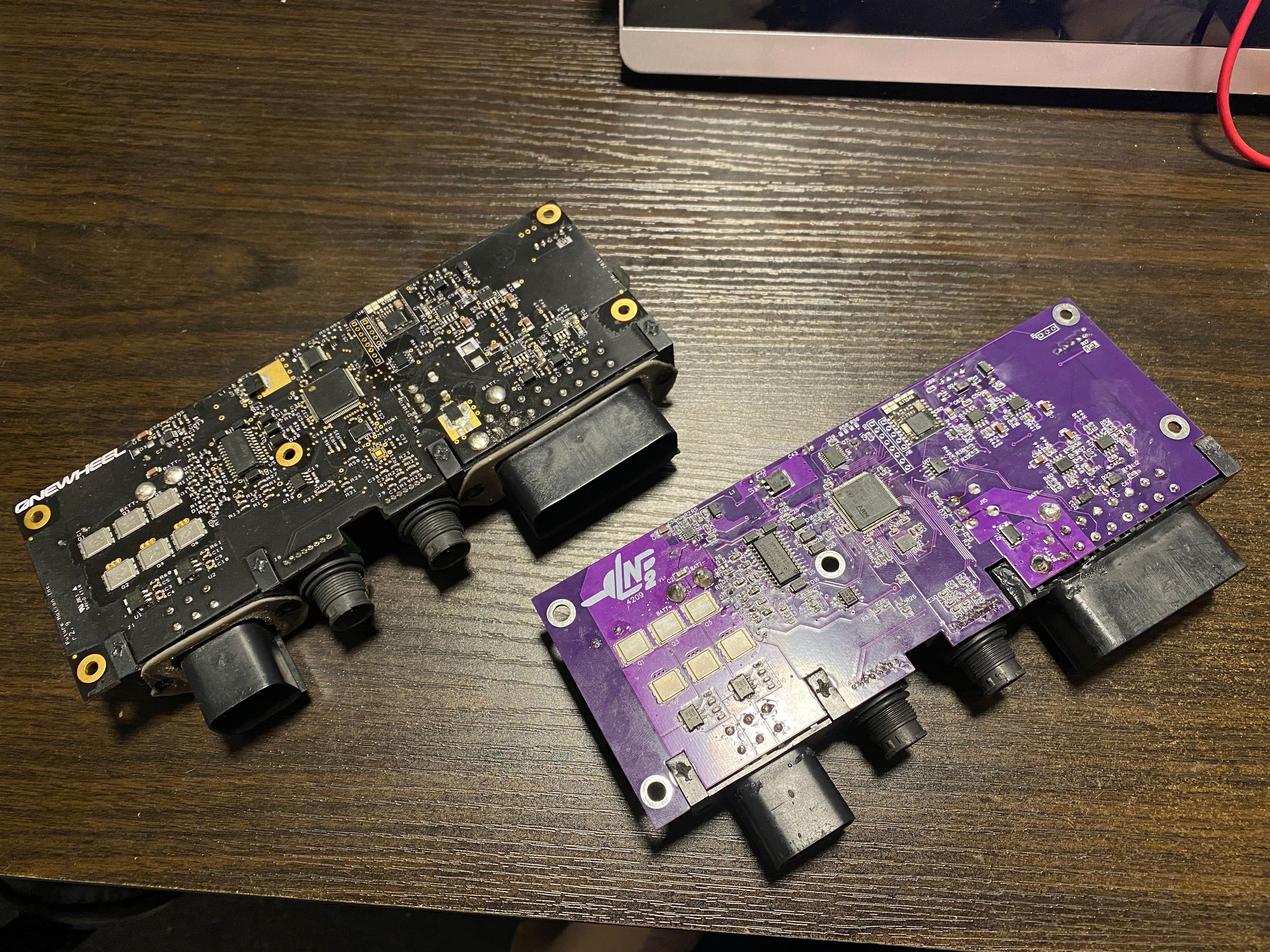
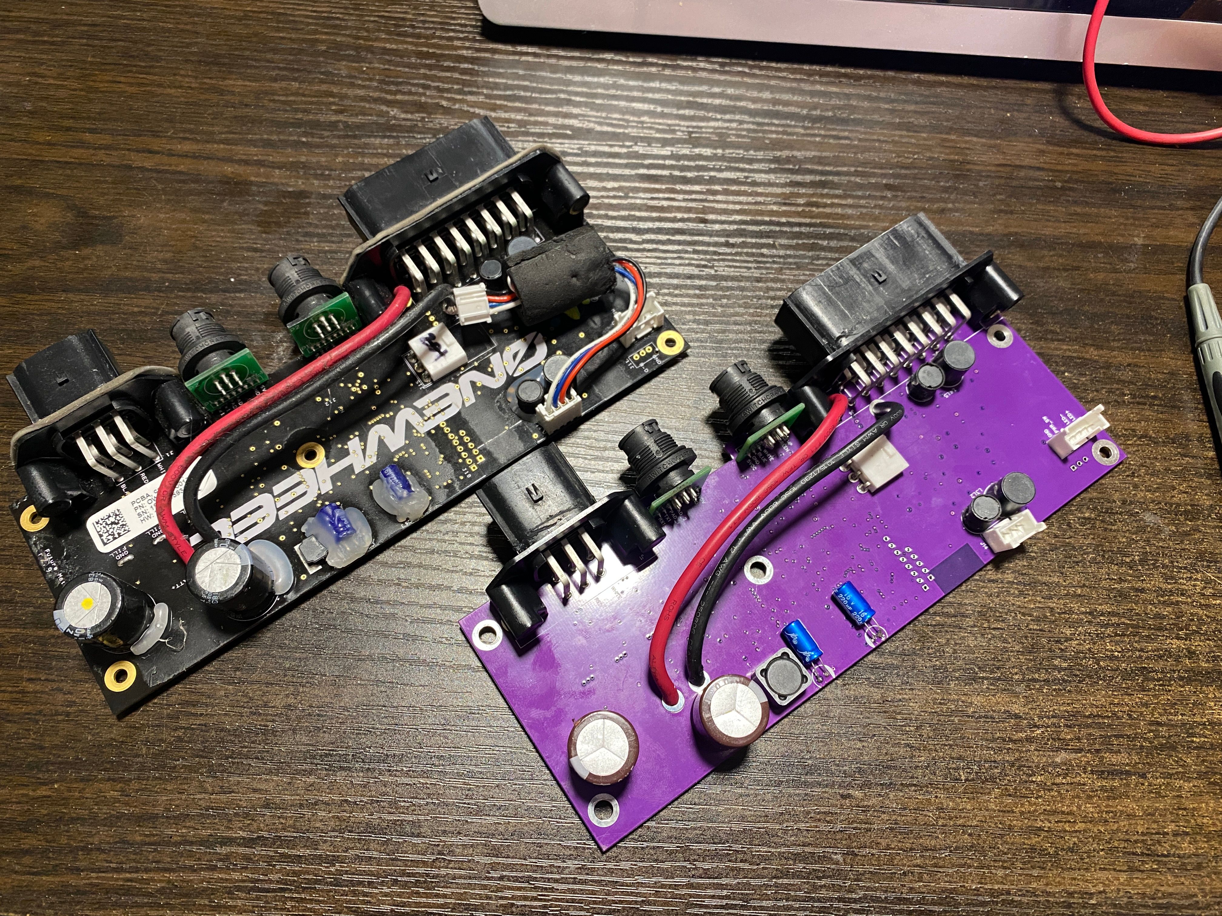
I did power her on...
aaaaaaaaaaaaaaand
... She didn't boot :((( No blinky flashy light.BUT she didn't catch fire so it's a win in my book. Good thing too since I was using the old "jam the charger in Batt+/Batt-" trick rather than build a battery and didn't want to blow my only XR charger. I'll slip my 30V bench psu in it next time so I can measure the current and figure out more while probing for expected voltages. It looks like the primary buck converter (U3) isn't doing it's job, that or L1 is being stinky.
Either way I need to spend some time diagnosing it properly and not just hiding at the edge of the desk with a pair of safety squints. I am after all a professional ^-^ Got myself a proper docs coat too so I can look all serious while I perform
surgeryrepair that some consider to be unnatural.