XR Error 21 (repaired)
-
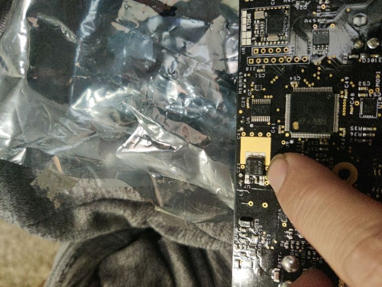
New patient has arrived courtesy of @HanahsDax which came with a few other goodies :)
An XR 4209 controller which has an E21 fault (charger connected) even when it isn't.
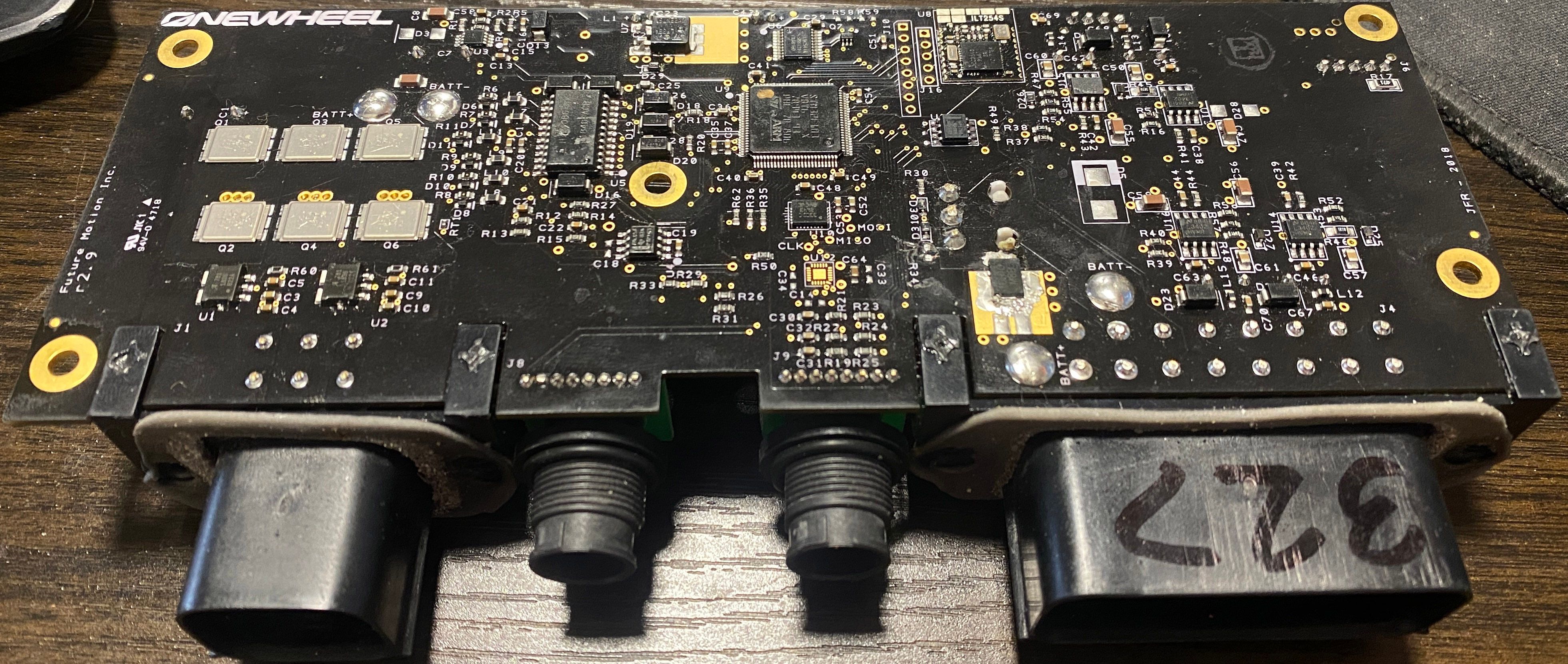
It has been through a previous repair where R34 was removed which is used on later models to detect if the charger is connected. Likely to limit range extension mods like CnR (charge and ride) and also to stop the 2-3 people that would manage to ride off still hooked up to the wall.
So far I've probed each cap (surface mount and through hole) and the diodes to check if there are any obvious shorts but nothing shows up.
After a bit of reading it appears that somehow corroded front or rear light bars can cause the fault to occur but I'm not seeing anything like that plus I have everything unplugged when testing.
Nothing seems to point towards anything obvious so this might require me to start pulling off chips to see when the fault stops and gives me a different error.
-
@lia said in XR Error 21:
also to stop the 2-3 people that would manage to ride off still hooked up to the wall.
lol
XR's got what plants crave!
-
That's some pretty ugly rework on that chip.
-
@stinkyface yeah I’m not into publicly shaming anyone but to think I had two different “repair” techs look at it here in the States is embarrassing.
-
@hanahsdax Agreed, I don't get into shaming mostly to avoid bad blood in the space.
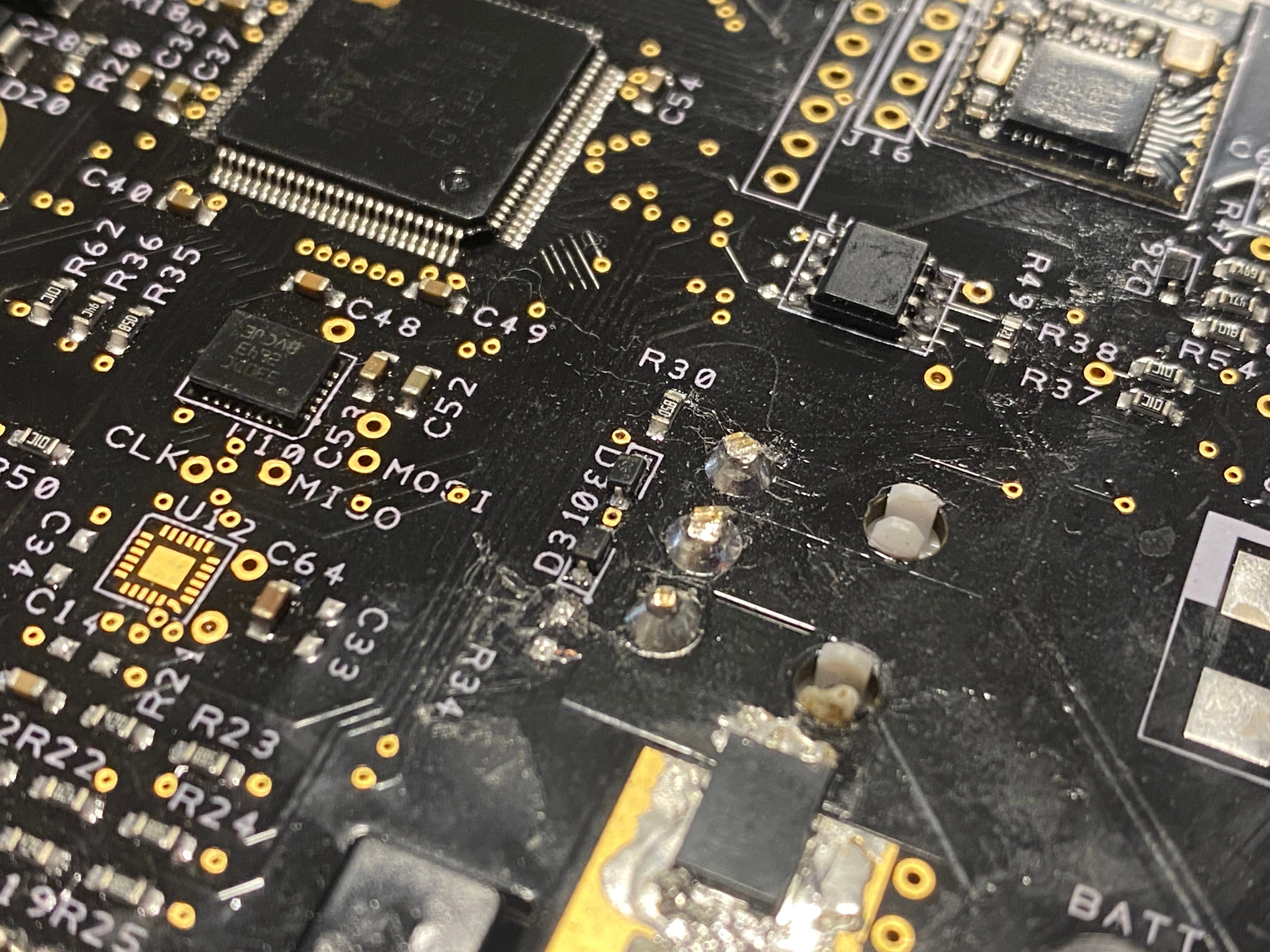
Did either replace U17 as that looks new and missing the coating that the other chips have? -
@lia honestly not sure what all was done to that controller. This pic was sent when one of the repair techs said it was fixed.
-
@hanahsdax Ah found it, LF33A is marked on it and appears to be a 3.3v Voltage regulator
https://www.mouser.co.uk/ProductDetail/STMicroelectronics/LF33ABDT-TR?qs=X0YN45AWjTaYMp6aKKXn6w%3D%3DProbing the output pin I can see it goes to the main ARM chip, U17 and the bluetooth module from what I can see so far.
On the Pint U6 appears to generate the 3.3v line and the 12v line which provide power to those too.If that died nothing would work, so guessing it was replaced just in case or it had legitimately died. Surprisingly it only provides 0.5A which isn't a lot.
Seems to work since I can talk to it so back to poking it.
-
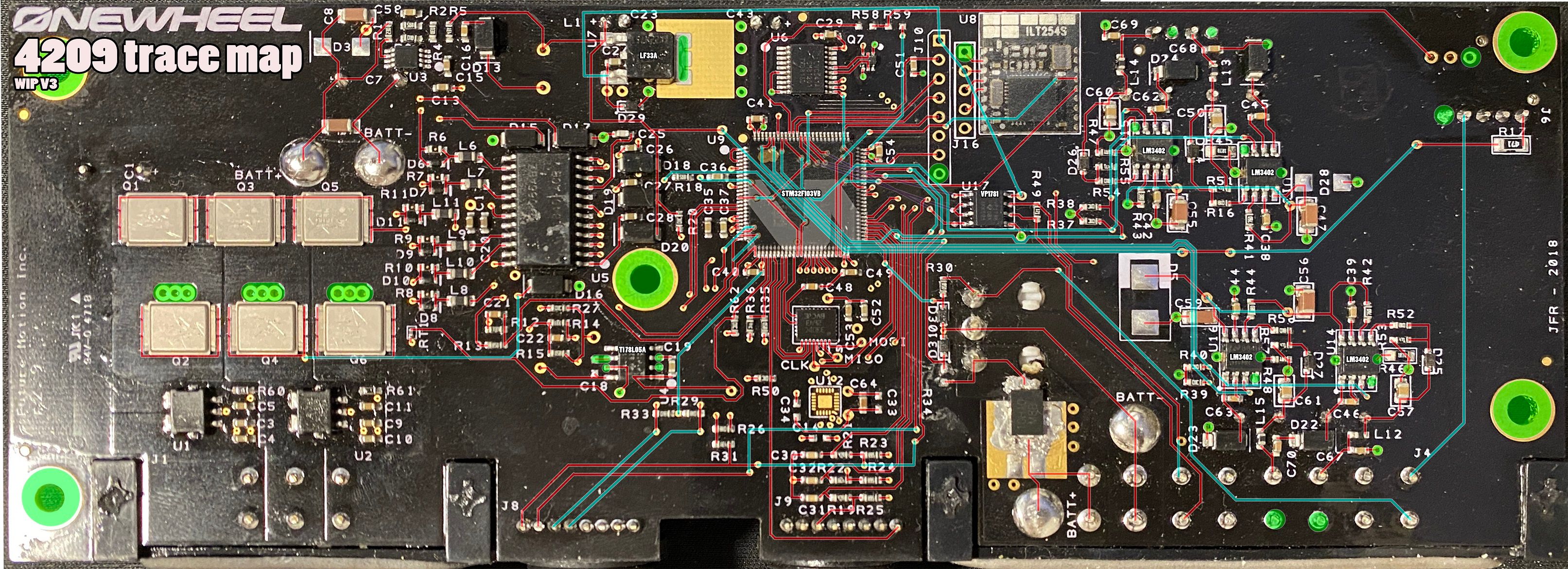
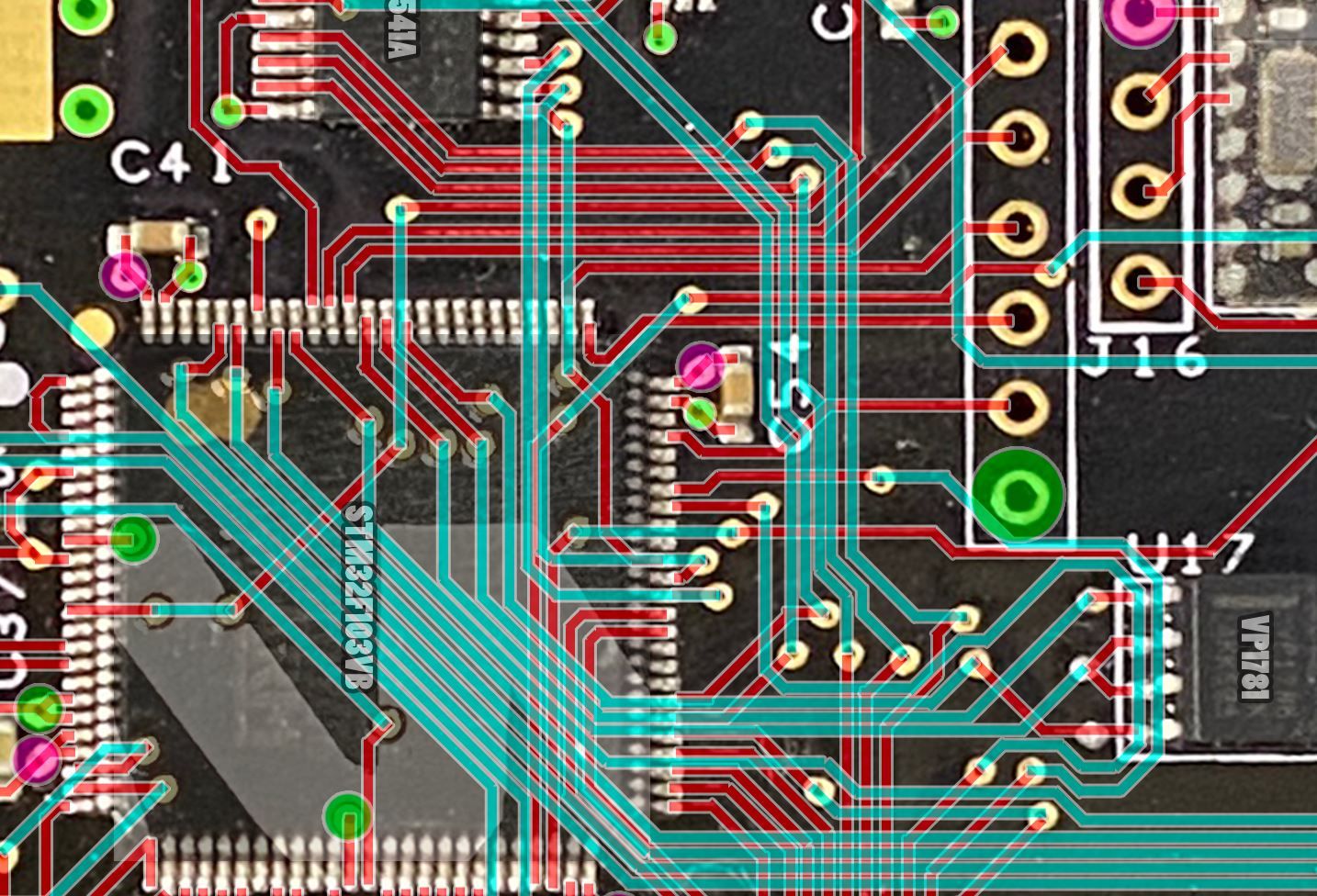
Still haven't found anything yet so been taking some time now and then to try map out all the traces. Bottom layer is easy since you can see those traces but the top layer is hidden. Without a dedicated x-ray machine I can't see the actual traces so will need to probe them out and then figure out how they probably route.
So far I've gotten this far trying to draw it out.
I'm assuming at least 3 layers but there could be a 4th or 5th voltage layer.
Red is the bottom layer
Blue is the middle layer
Green is the top GND layer
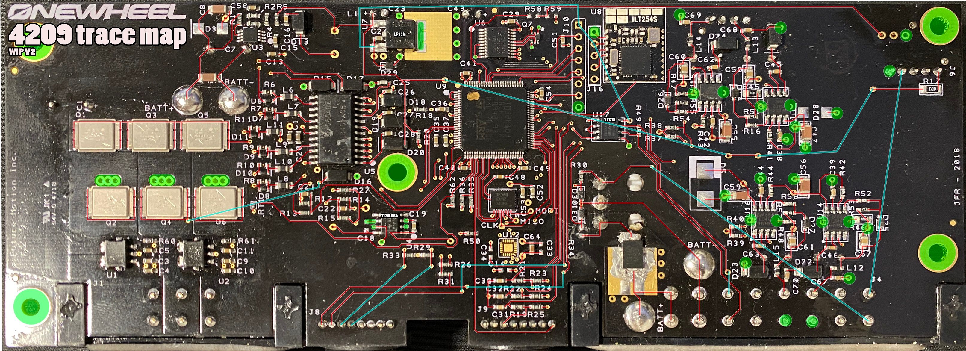
Saw a vid by William Osman making his own medical xray but I think I'll avoid potentially irradiating and destroying equipment around me ;)
This'll likely not lead to me finding anything but it'll give me something to idly do, be useful for someone else and more importantly keep my brain entertained long enough for it to think of something better.
-
@lia i'm starting to think ur not a system administrator at all...
XR's got what plants crave!
-
@notsure Best news I've heard all week!
That said what do you think I am then~? -
XR's got what plants crave!
-
@notsure Omg yes please!
-
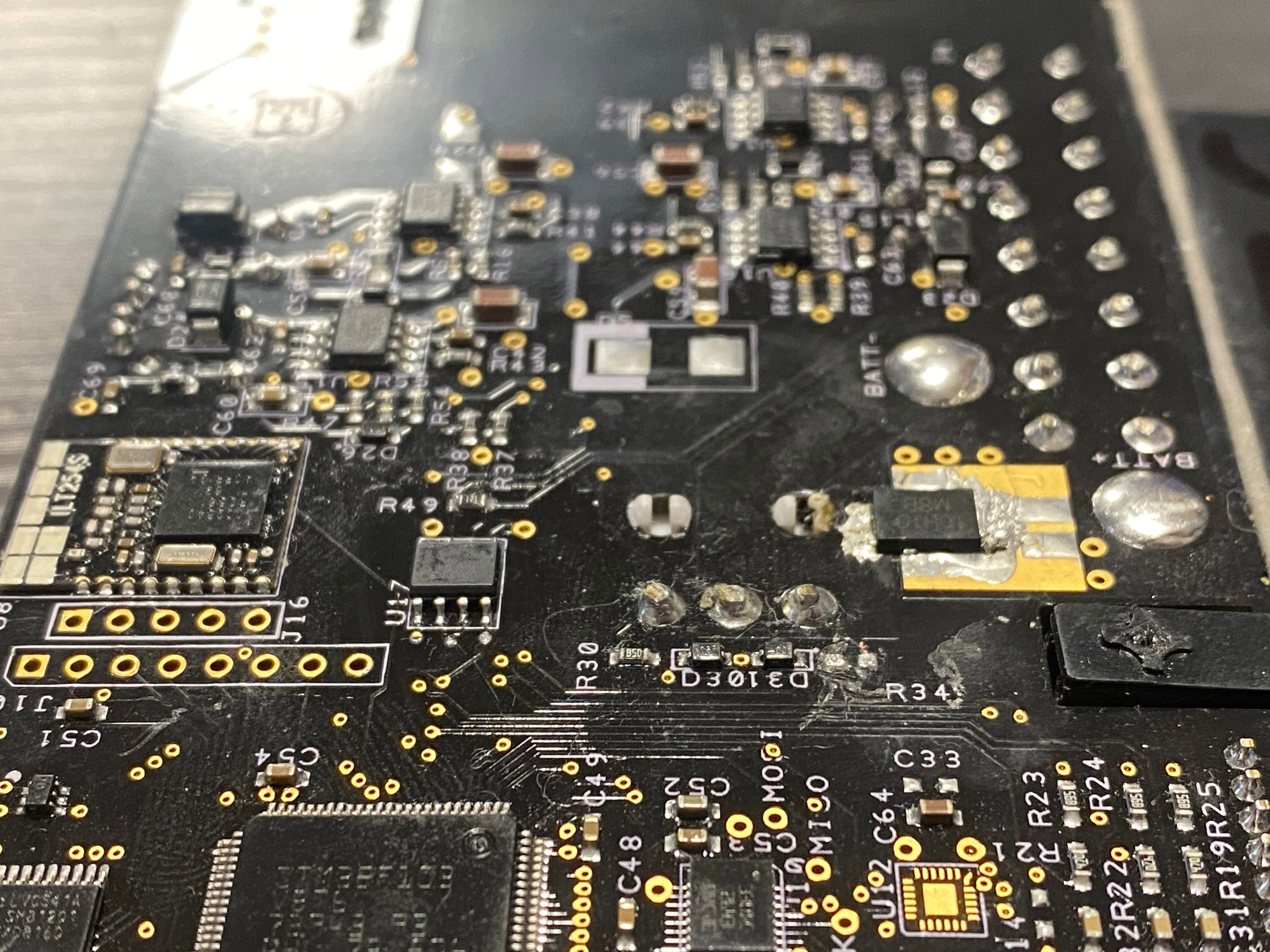
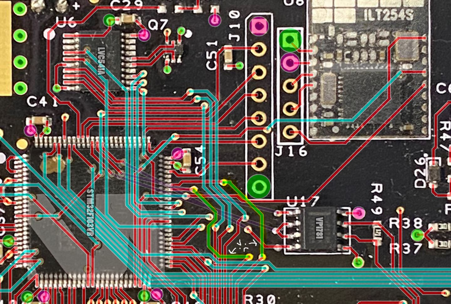
I think I found it!
The LED driver circuit has parts of it where both ends of a cap ground. This literally makes 0 sense so I think that's the problem.Looks like I had my probes round the wrong way. It only goes to ground in one direction so there must be a diode going back to ground off Vin that I was catching.Appears to be on the front side of the driver circuit, I didn't realise what it was till drawing the traces.
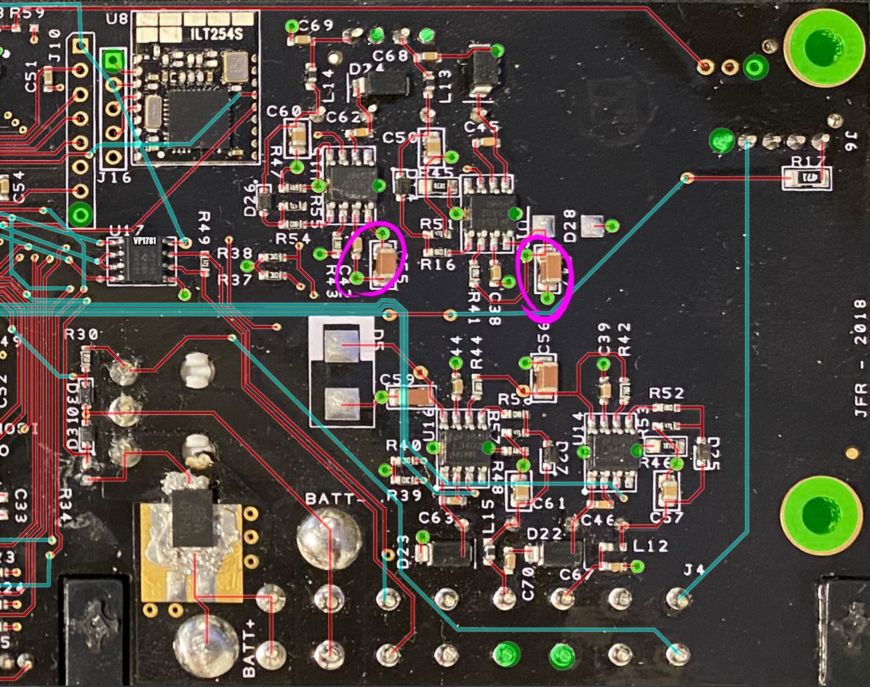
Bare in mind the blue traces are my guesses. There are only certain ways they can route without interfering with the other traces on the same layer and the vias that go throught the whole pcb.
.
Edit 1
Still mapping stuff out... All I have to say is.... why.... WHY is this so confusing!
Bare in mind the blue lines are guesses (as are any red that are under a chip). I can tone them out but I can't see through objects :(.
Edit 2
Going to stop for tonight, hit the wall trying to trace how the maps back to the chip without hitting the other traces. There must be either another way some of the other traces route or there's another layer somewhere. For now I've put those as purple traces.
I do feel that maybe there is a 3.3v layer on this PCB since it goes to so many other pins on a hidden layer that seem to conflict with the other trace paths. Suggesting it could be a 4 layer PCB. -
@lia You have so much dedication and patience, kudos to you!
-
@lemur Thanks :)
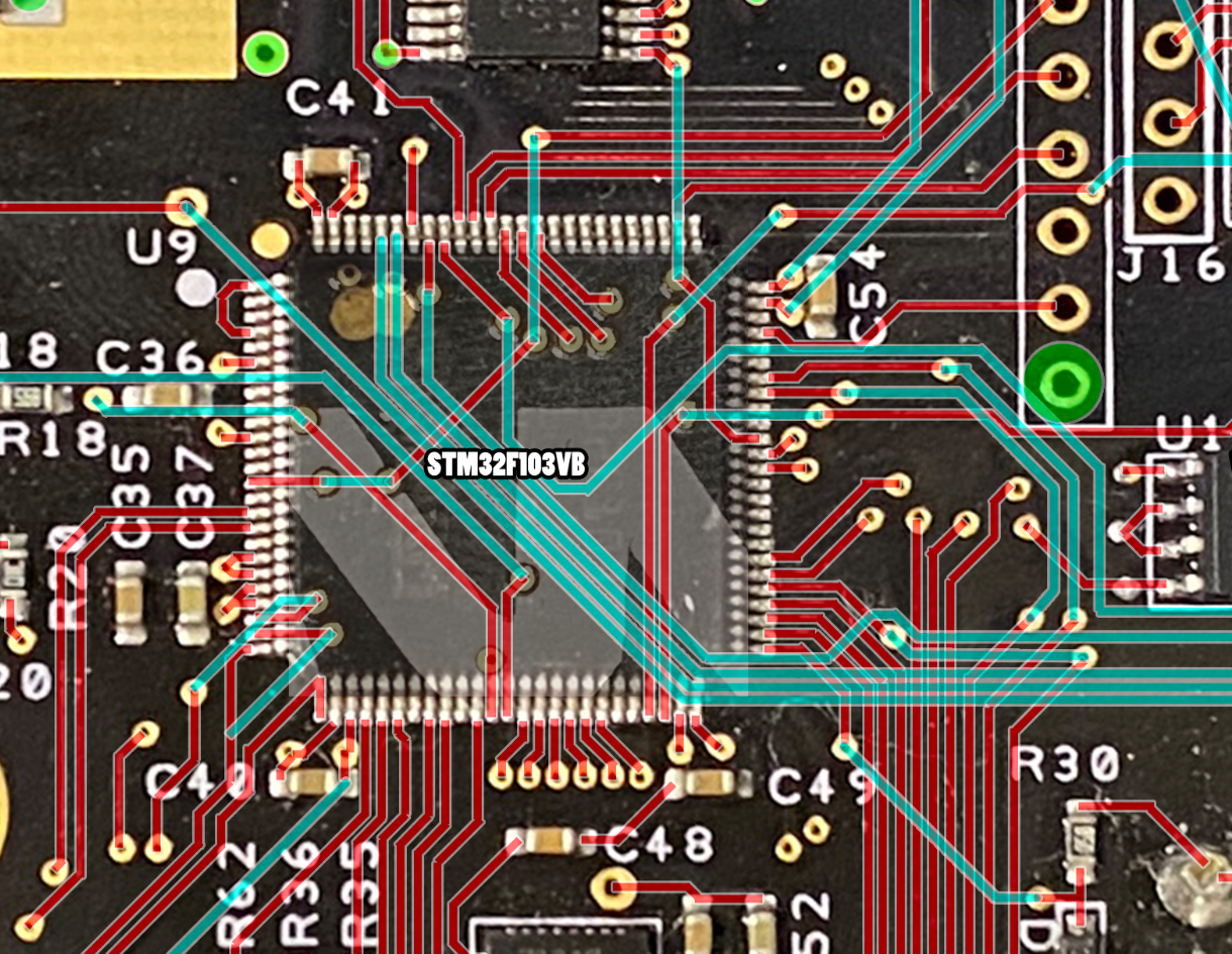
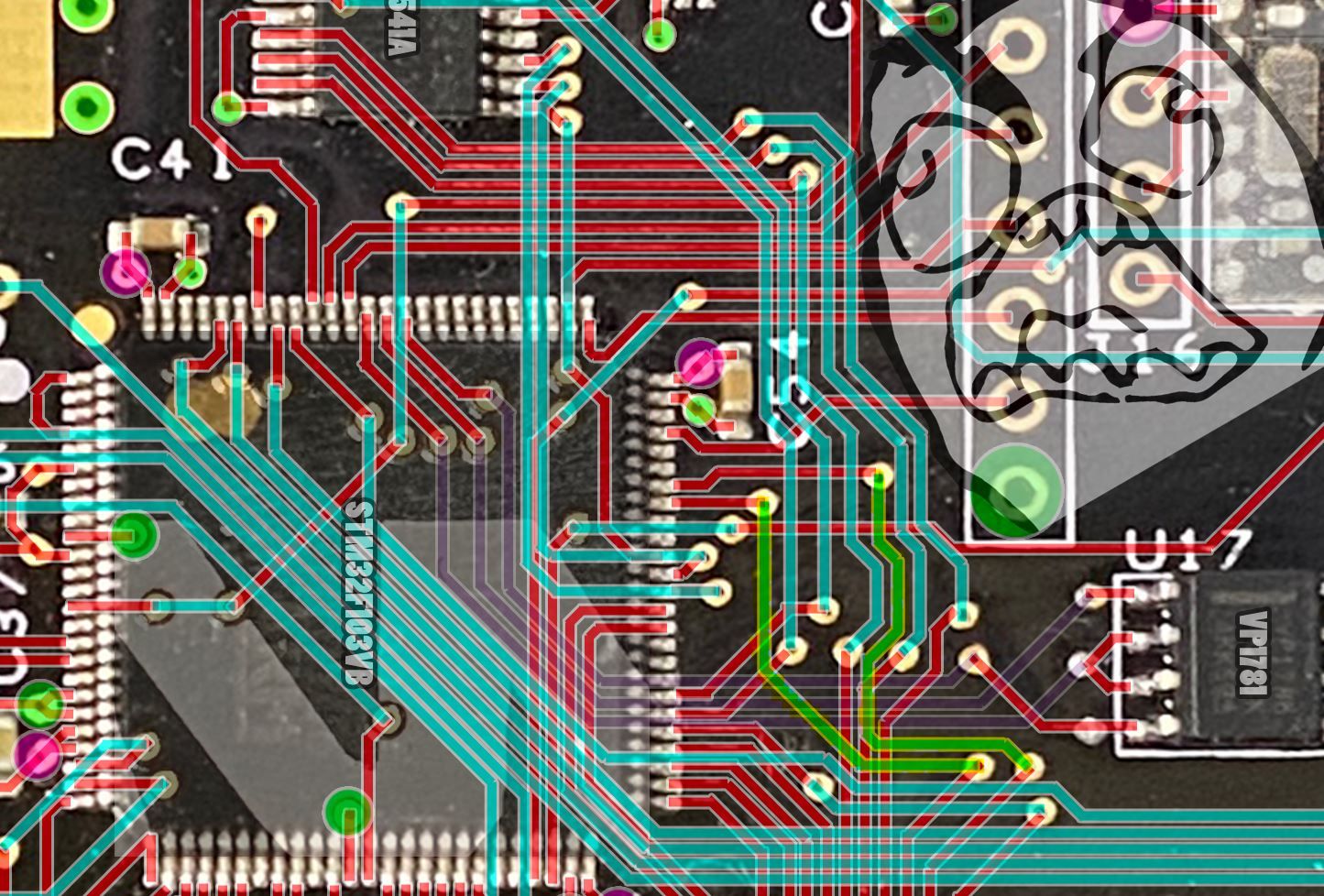
I know a schematic for the controller will allow 3rd party repair to get much better so putting in the effort seems like the right thing to do.Still working on the spagetti part near the ARM chip. Got maybe 1 or 2 traces not routing on appropriate paths making some other traces hard to connect however I'm nearly making sense of it all.
Highlighted 2 traces I think are wrong (yellowy-green with the angee face pointing at them) that is stopping me route the 3 traces for the BMS/Controller communication. Hats off to whoever painstakingly routed these traces, no way did an automatic tool do this.Full image for V4 below.
Red is the bottom layer
Blue is the middle layer
Green is the top GND layer
Pink is 3.3v that I haven't decided how they route yet
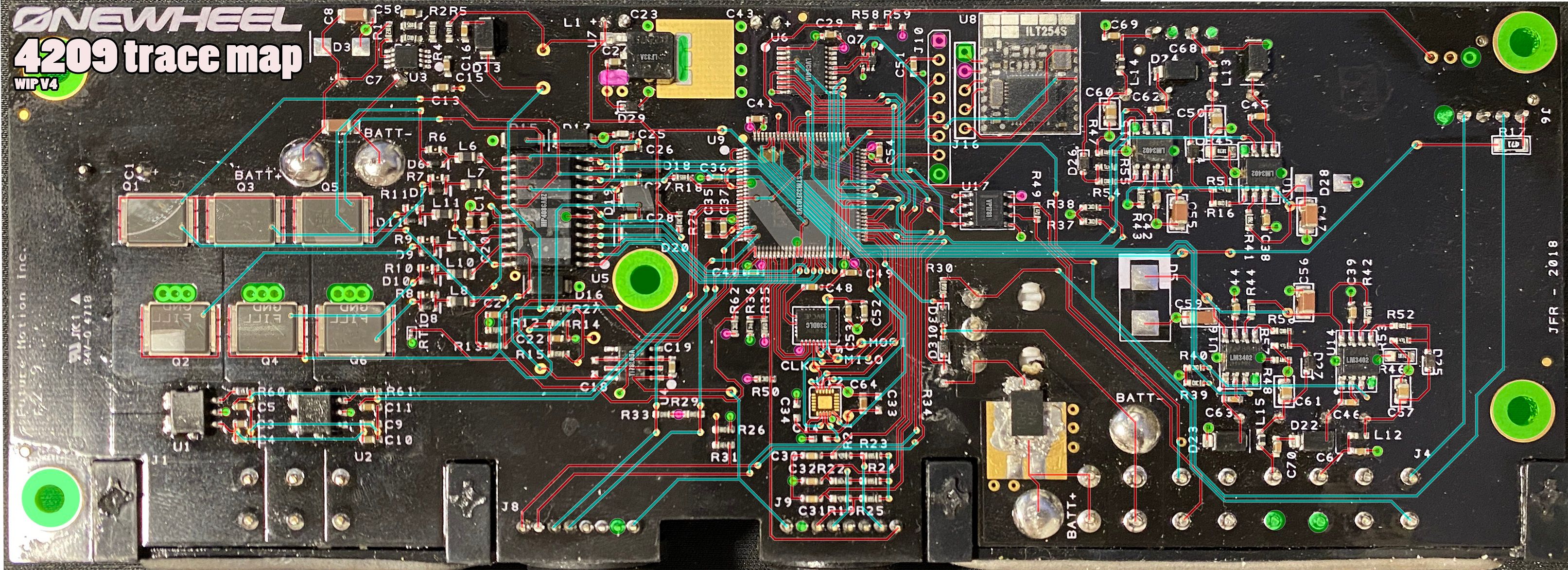
I can safely say I am much more familiar with how this works even if I don't understand what some parts do exactly. Will probably be able to give a full pinout for it soon or recreate the PCB as a gerber file for 3rd party manufacturing 0:.
Edit 1
Thought I had it... AAAAAAAAAAAAAAH
.
Edit 2
Okay I figured out a way to route the blue traces that makes sense and isn't too weird. There are definitely ways the via's could have been placed to be more sensible but... oh well.
-
@lia In awe, I am, at your ability to figure these workings out!
-
@s-leon Thanks :)
I like to think of it like those games where you try to arrange pipes to connect the inlet to the outlet. Just in this case there are lots and I have to find where the inlet and outlets are. -
@lia I reflowed the solder on a ASIC miner hashboard today and fixed an intermittent issue. Was feeling awesome then read this post and reaffirmed I'm not even on the same playing field as you. 👏
-
@stinkyface Congrats on the repair! Reflowing isn’t nearly as easy as they make it look on YT.
Funny side note, a few years ago I absolutely toasted a Toshiba laptop that had a lifted CPU… but because I’m a moron I used a heatgun @400c and some tin foil to try protect the rest of the board from the heat.
That day I learnt what popcorning a pcb looked like.Since then I got myself the right tools for some reflowing. CPU reflowing is still out of my league.
-
I have spent this entire time trying to find where the LED drivers get their power from.
Thought I already checked this but apparently not since I accidentally discovered they're driven straight off the main battery rail. I am omega dumb.I now somehow have to figure how Batt+ reaches an of the vias on the LED side
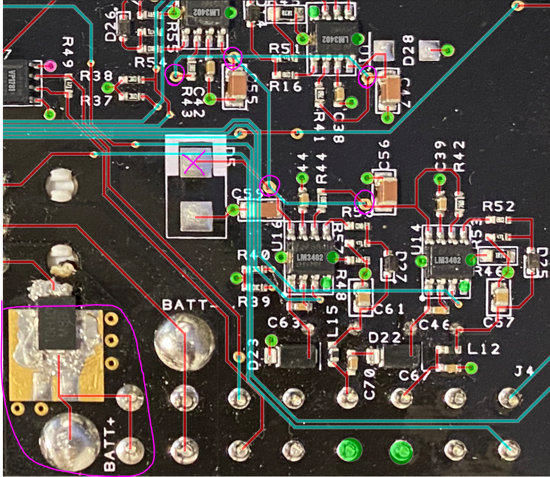
Can't go to that pad for D5 since there is no surface trace leading to it or a via under it to connect to.Presumably the 4 blue traces going vertical between them route differently but I can't see a valid way to move them in a way that exposes a direct path between them. I imagine there is a sensible pathing that's just been clouded by my existing guesses, sort of like trying to solve a Sudoku by guessing a few numbers that later comes back to haunt you on the last few empty squares.