The Onewheel GTXS (Half scale GTS)
-
@lia said in The Onewheel GTXS (Half scale GTS):
22 hours later and I have me a mean looking tire to go with the little guy.
Brava! Looks awesome. How soon till I can buy one on Amazon?
XR's got what plants crave!
-
@notsure If only 😭
-
@lia Amazing work!
-
Looks so good!!
Onewheel needs a super brain like yours. -
Thanks @Lemur and @Wheelwizard 🥰
If they ever open up a department for "toys" I'm their gal 🙏 -
Nearly forgot to make the maghandle. That'd have been tragic.
It's surprisingly fun to play with and snaps back nicely with 2 tiny 3mm magnets tucked away in the axle block and handle 🥰
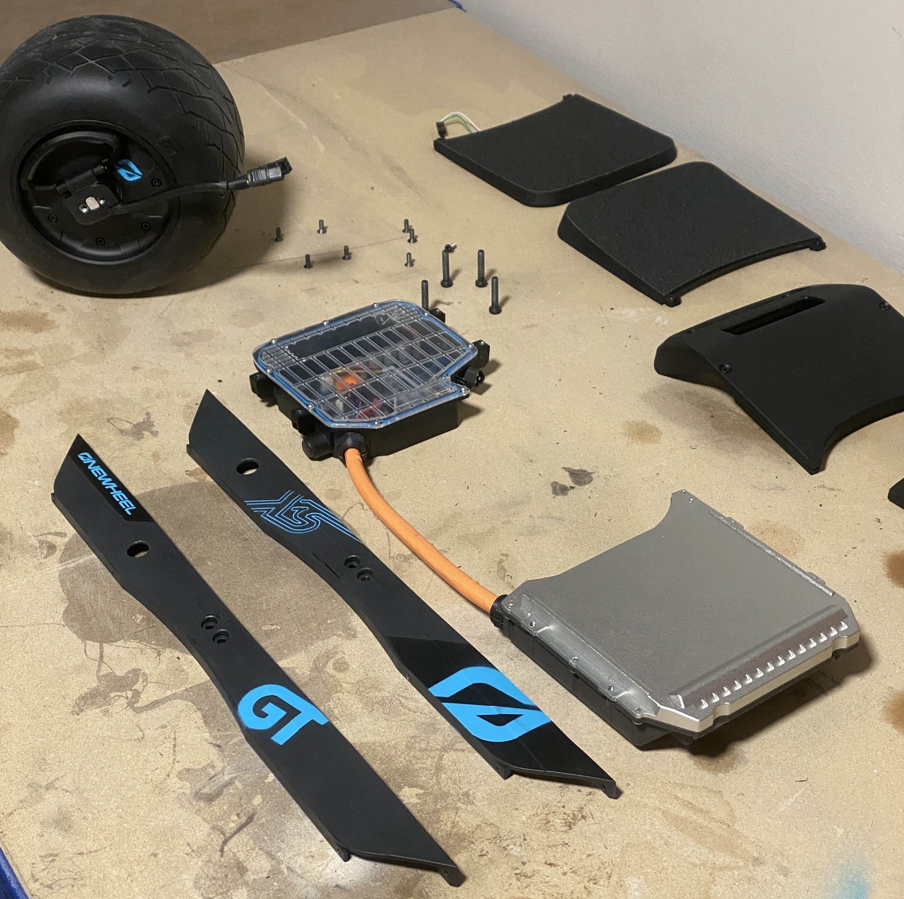
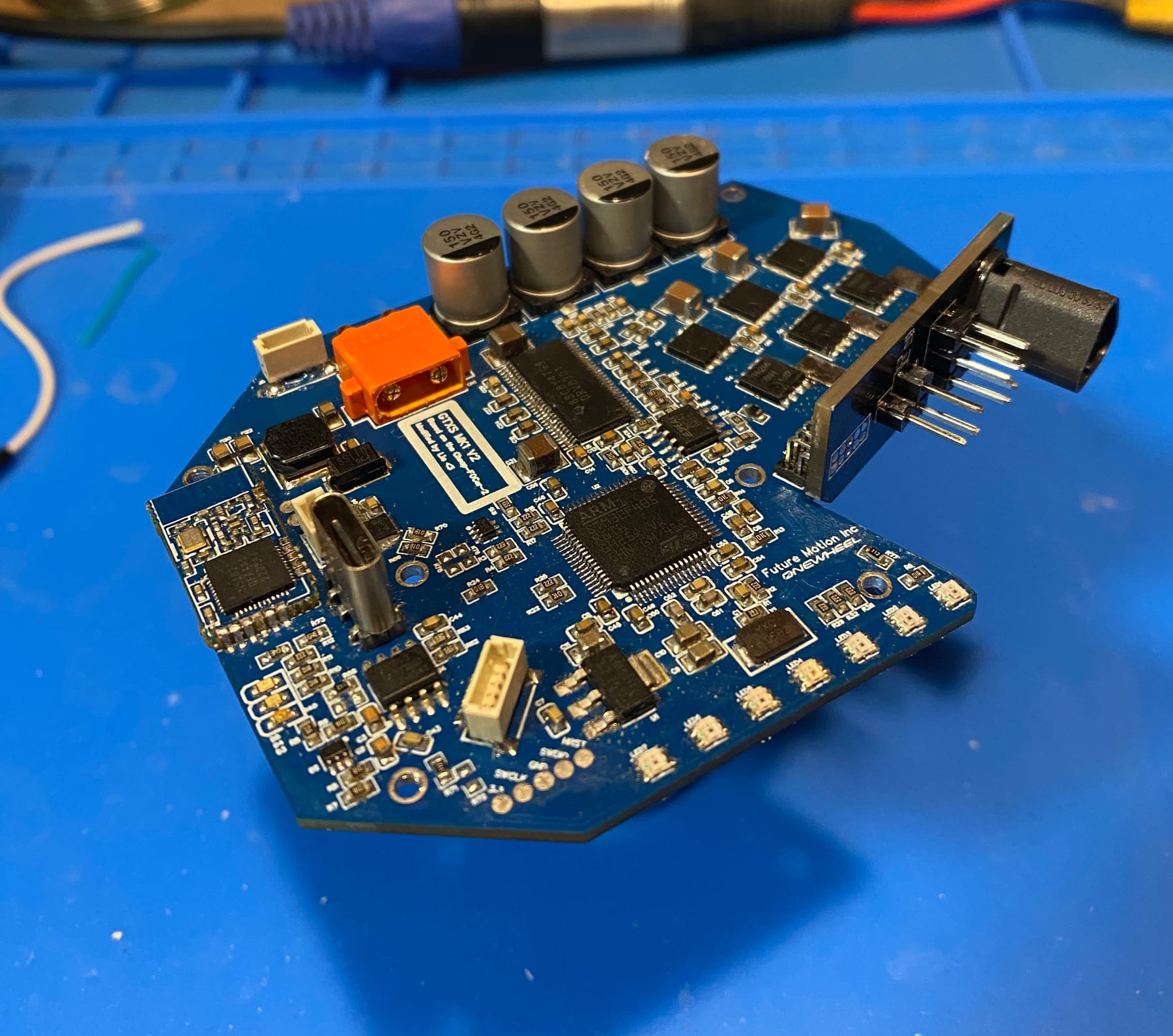
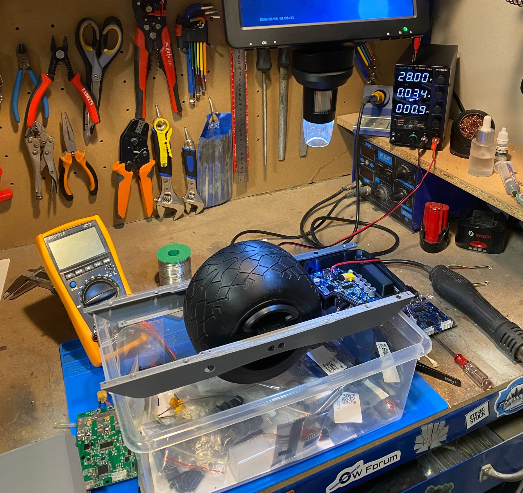
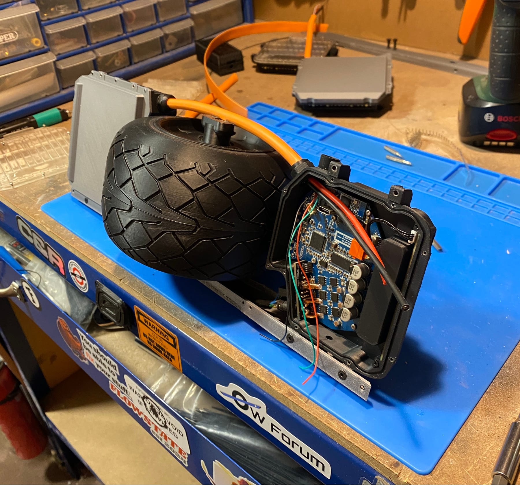
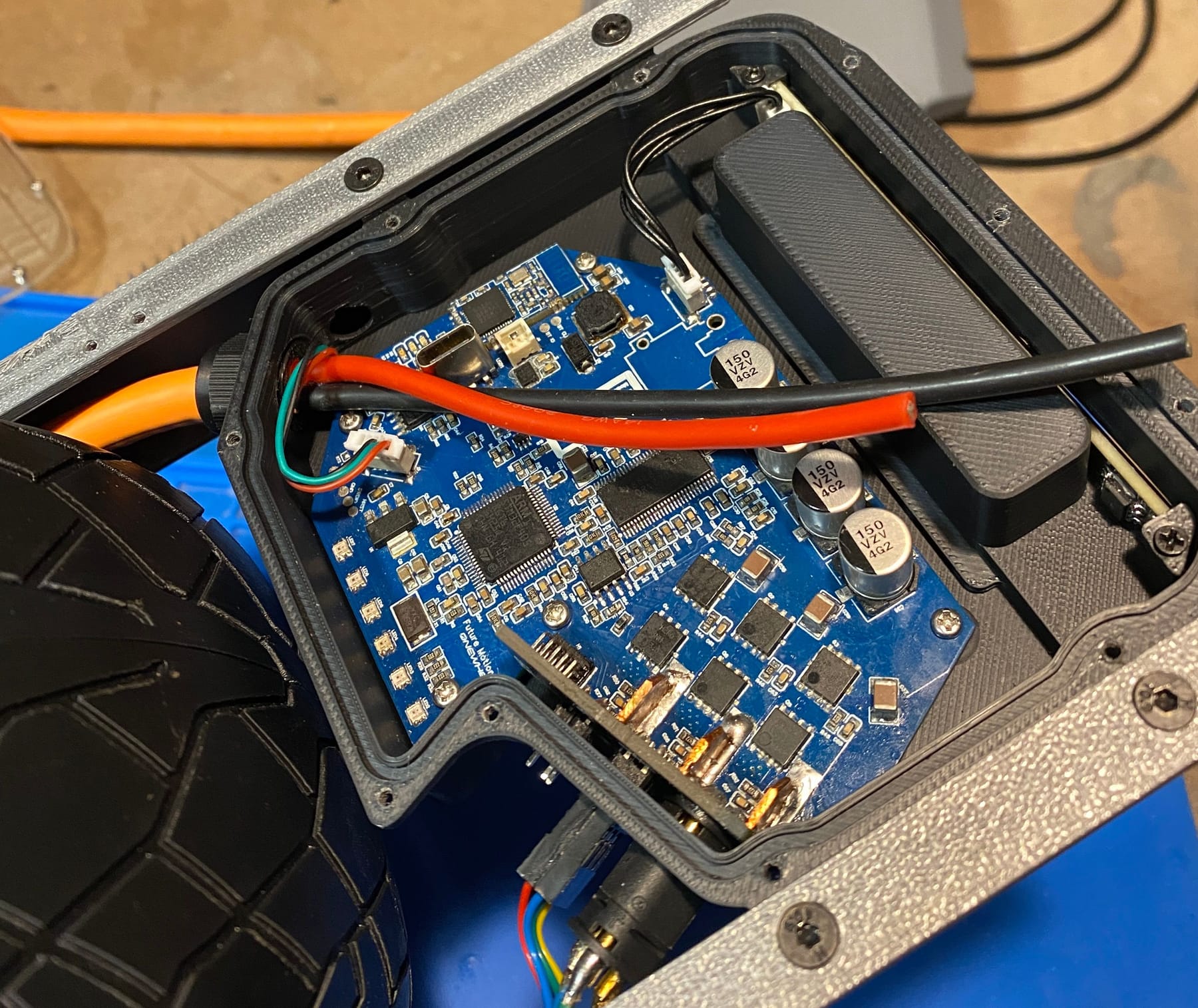
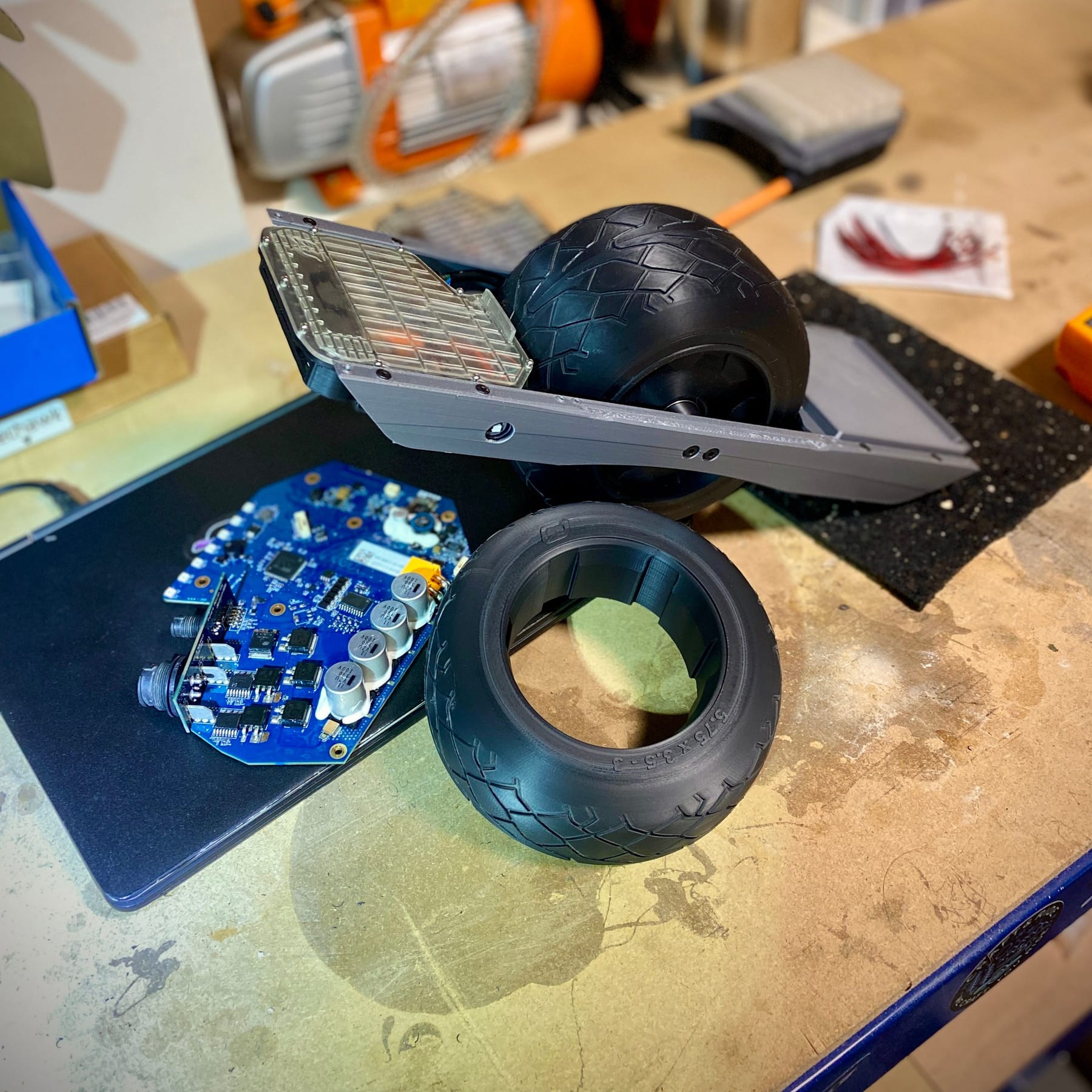
Probably gonna leave this as plastic because it looks like hell to machine which means expensive.All the current bits laid bare and it's very familiar looking. Like you'd just gutted an actual GT.
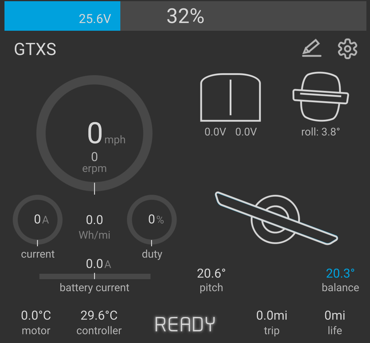
A lot less physically going into this than the XS but don't be fooled. The lack of components doesn't mean this has been any easier. That custom controller still needs populating and testing which has taken the majority of my R&D time.Speaking of testing. 42km/h freewheel speed ain't bad especially with just plastic test pieces and an incomplete axle 😅
With 35 amps max current available and just shy of 30v this little monster is not a toy. Still cute, but a right ankle biter if it ever ghosted.
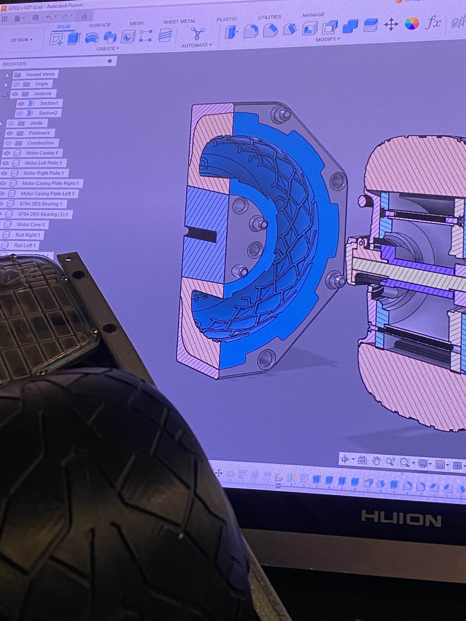
Finally... I can safely say I have nearly completed the CAD.
I wanna go with recurve rails but I have no dimensions for the angles and where they are in the rail so I might ask (beg) FM for a rail. Also wanna give that rear pad the high kick version for extra flair. I am after all trying to make a tiny GTS so why not give it some of the cooler accessories.
I was considering FST but that's a lot more faff and I'd have to get even more creative with a sensor 😩 It's huge maybe especially since it's not like your hands could take advantage that well. -
Hiiiii guys.
Guess who forgor to update the thread again 🥺 (It's me, hi, I'm the problem, it's me)
I'm really bad at keeping this updated. At least you all get a condensed version of events this way.Let's hop in the time machine and zip back to December last year~
@cheppy44 was over here and we decided to take a crack at the custom VESC. We prepped another cheap foccer 2 as the transplant patient provided by Quinn 🙏 (thank you again)
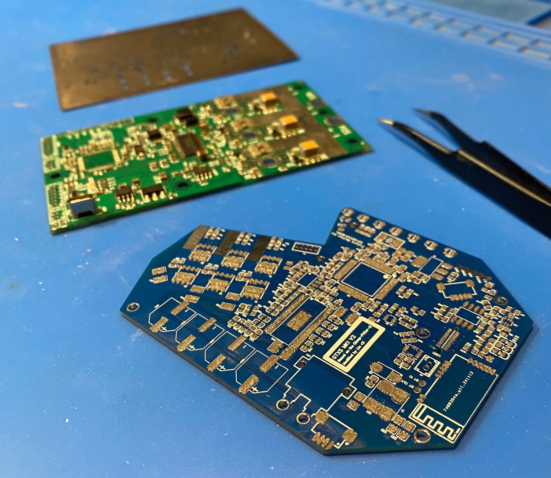
Taking the parts off was made easier by the big hot plate I got but by the end of it this PCB was cooked.
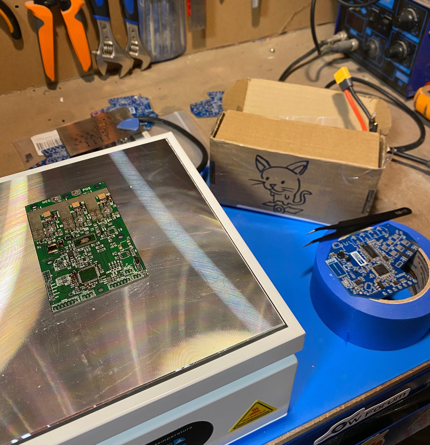
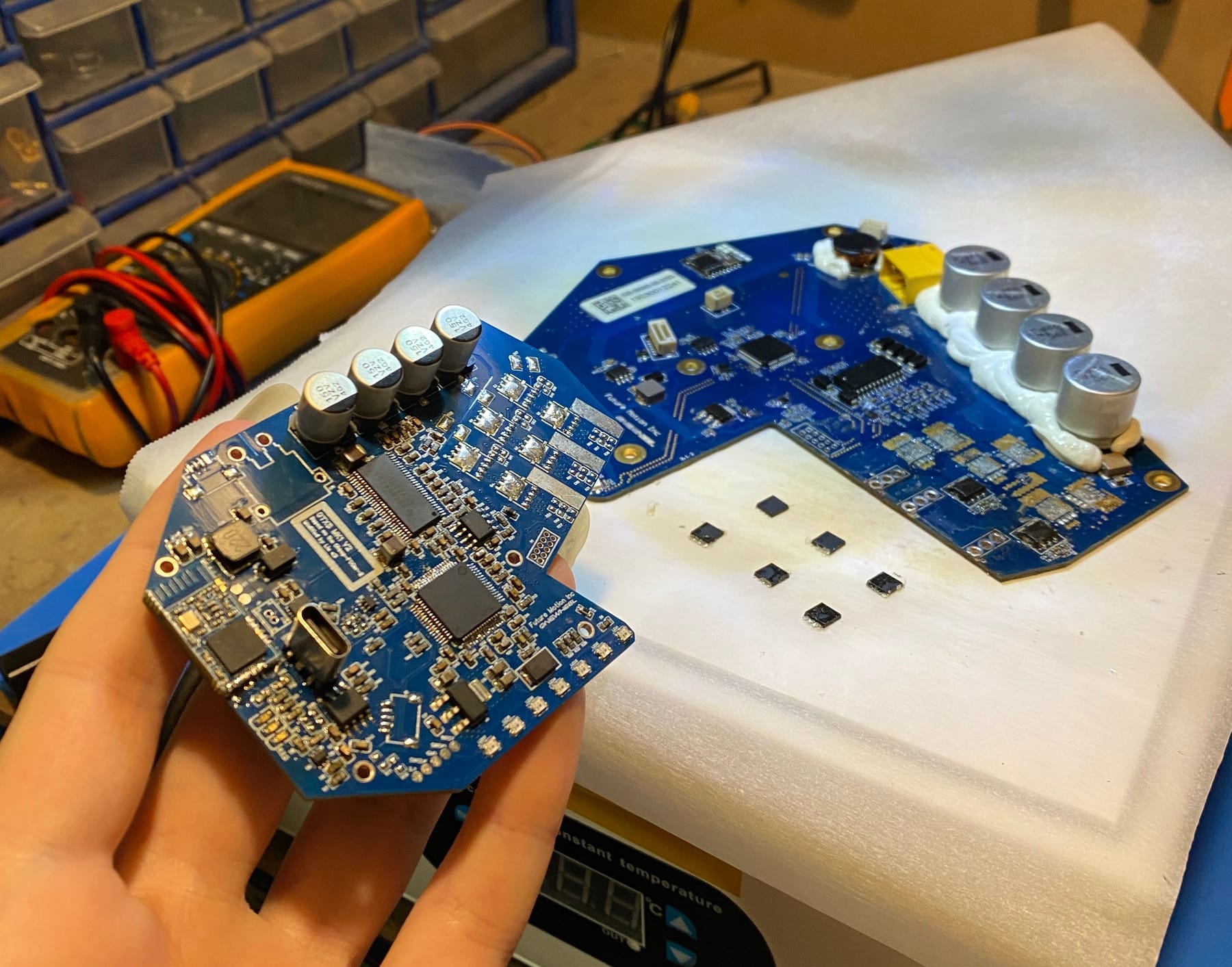
We got everything moved over and just needed a few special components. Compared to a can of Pepsi it's absolutely tiny 🥰
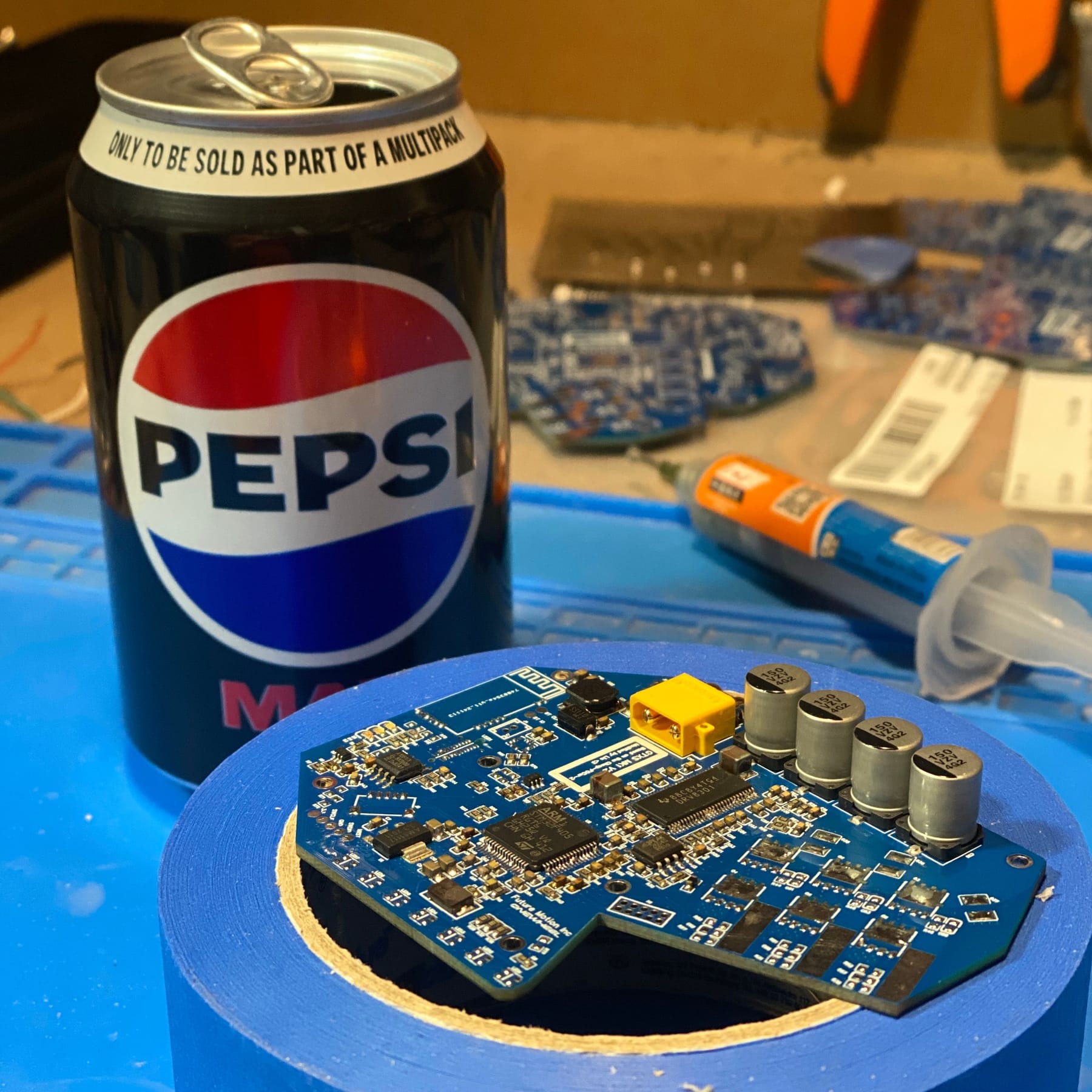
A broken pint was used as a donor for the mosfets. When designing the board I thought it'd be funny to use actual FM parts in the build where I could.
Other than a bodge wire on the IMU which took way too many attempts than I'm willing to admit the PCB was perfect.
But no like seriously we spent days trying to get the IMU to work 😭My resistor sample book somehow managed to package 51k resistors where 1k ones should have been so that's what the resistor is off to the side. I didn't have any others spare at the time to swap >.> But once it was in the LEDs worked fine too.
Head and tail lights needed testing so during Christmas we got it to demo itself being festive 🥰
The white LEDs are not lit in these with how I set it up. The first LED in each headlight are sent to a ws2811 chip that on the blue pin goes to all the white LEDs. With this I can control the high beam by setting that LED in the chain to anything including a blue signal and it will light up. This way when front and rear swap so will the main beam without any additional code since red has no blue but white does. In code I can then pull the main beam LEDs to 0 if I want to toggle them off which I will do with a custom version of refloat I'll get to once this is mostly together.At some point in adding the daughterboard a single lil solderball managed to kill the main STM chip. It booted up and then upon trying to hold the motor sent like 29v to the chip down one of the sense pins. Oops. Cooked it :( After some tears I did manage to pull off the old one and put a fresh chip there then used an STLink to flash it.
With a bit more faffing we had it running. There was another mistake on the daughterboard where the pins were mapped backwards so we had to run it using more bodge wires while waiting for the new ones to show up.
Nick had to leave mid January and things took a brief hiatus while I readjusted to being here on my bill. But eventually I got back into the swing with the arrival of the new parts.
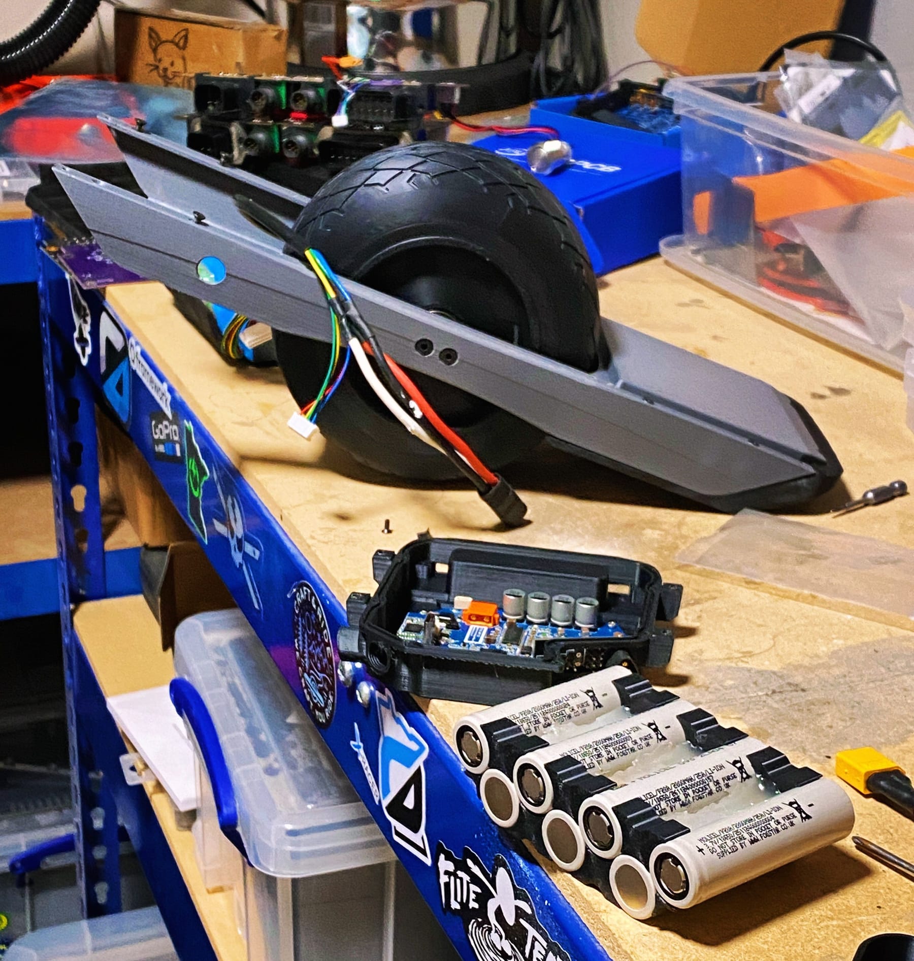
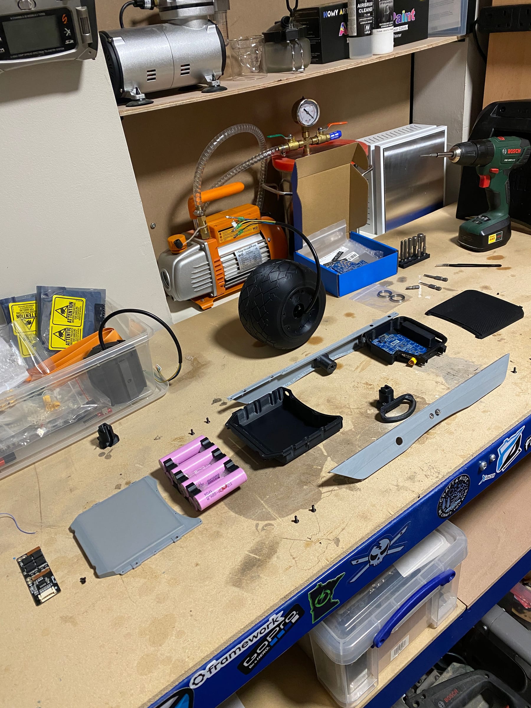
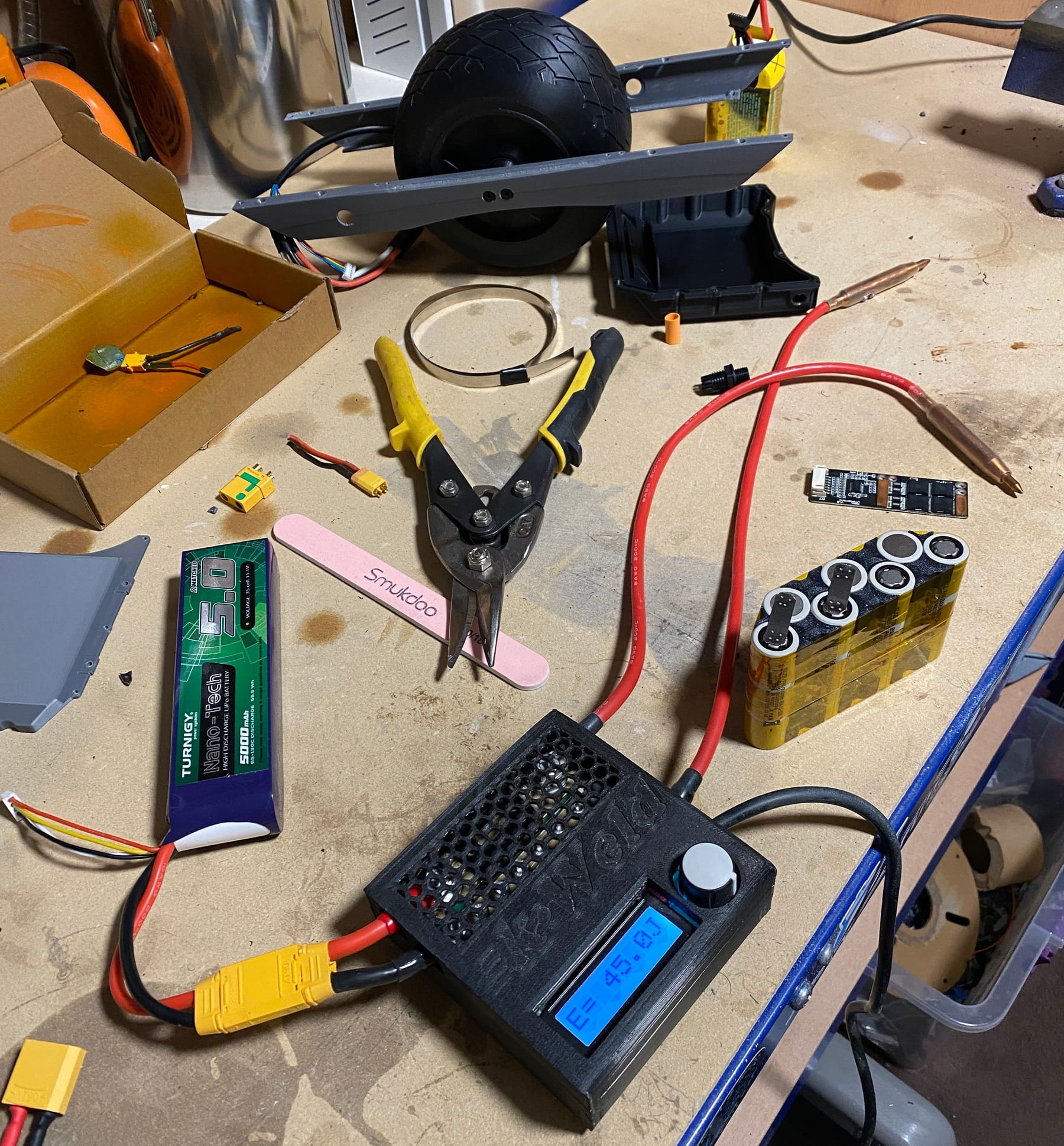
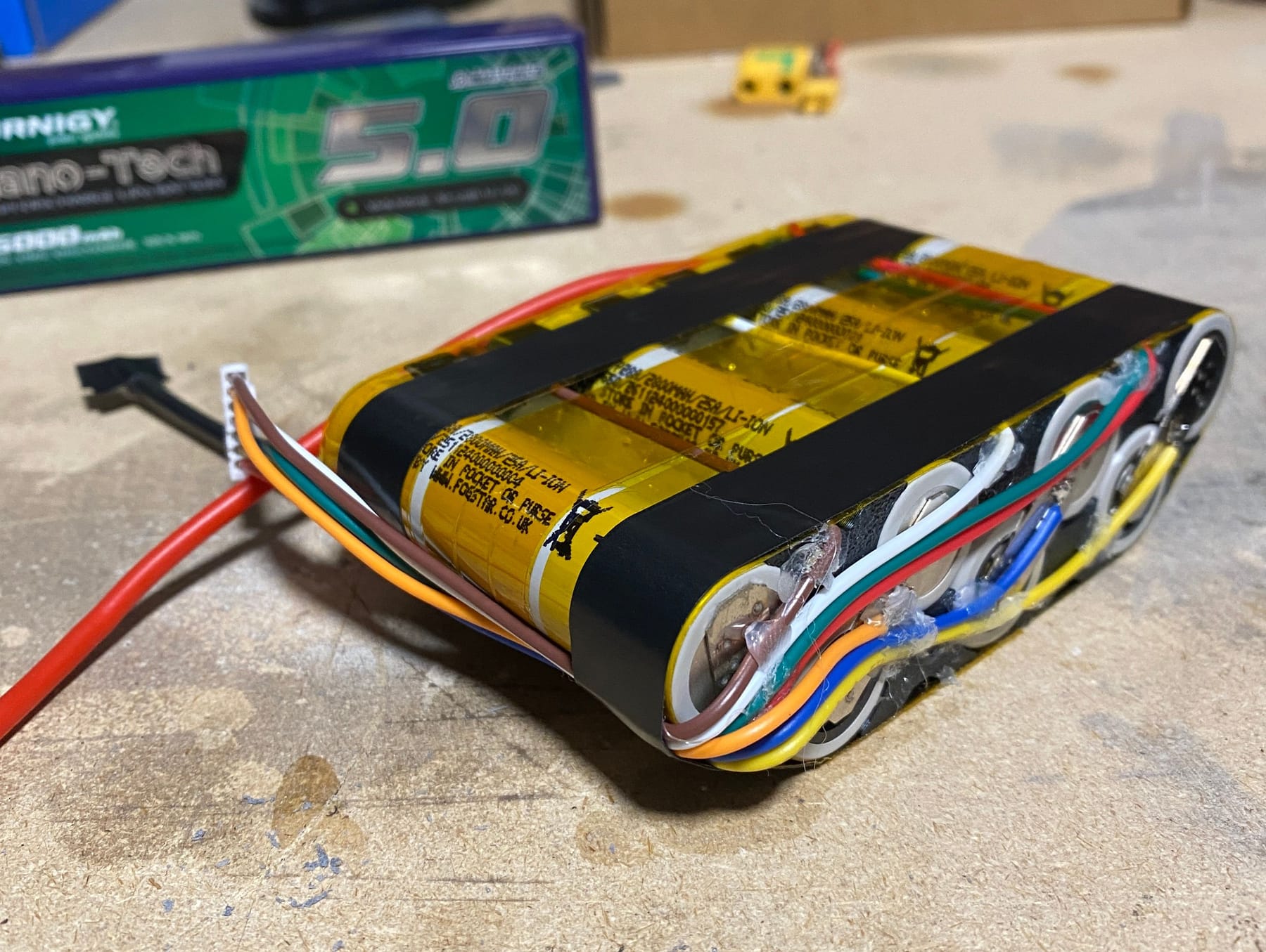
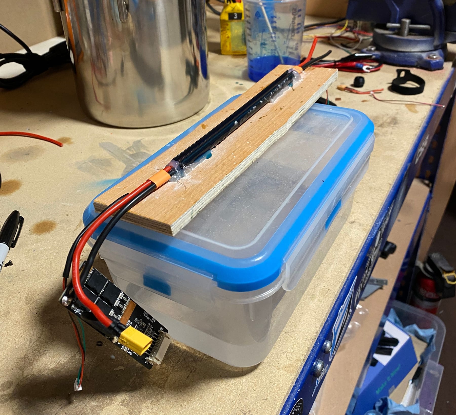
It was however time to stop faffing and get on with the battery. We tried it before Nick left but my 2x3s LiPos were out of commission and some 6s ones I got were too much for the KWeld. Instead with a new Turnigy battery I got the welder working an was ready to get the 7s1p pack made.
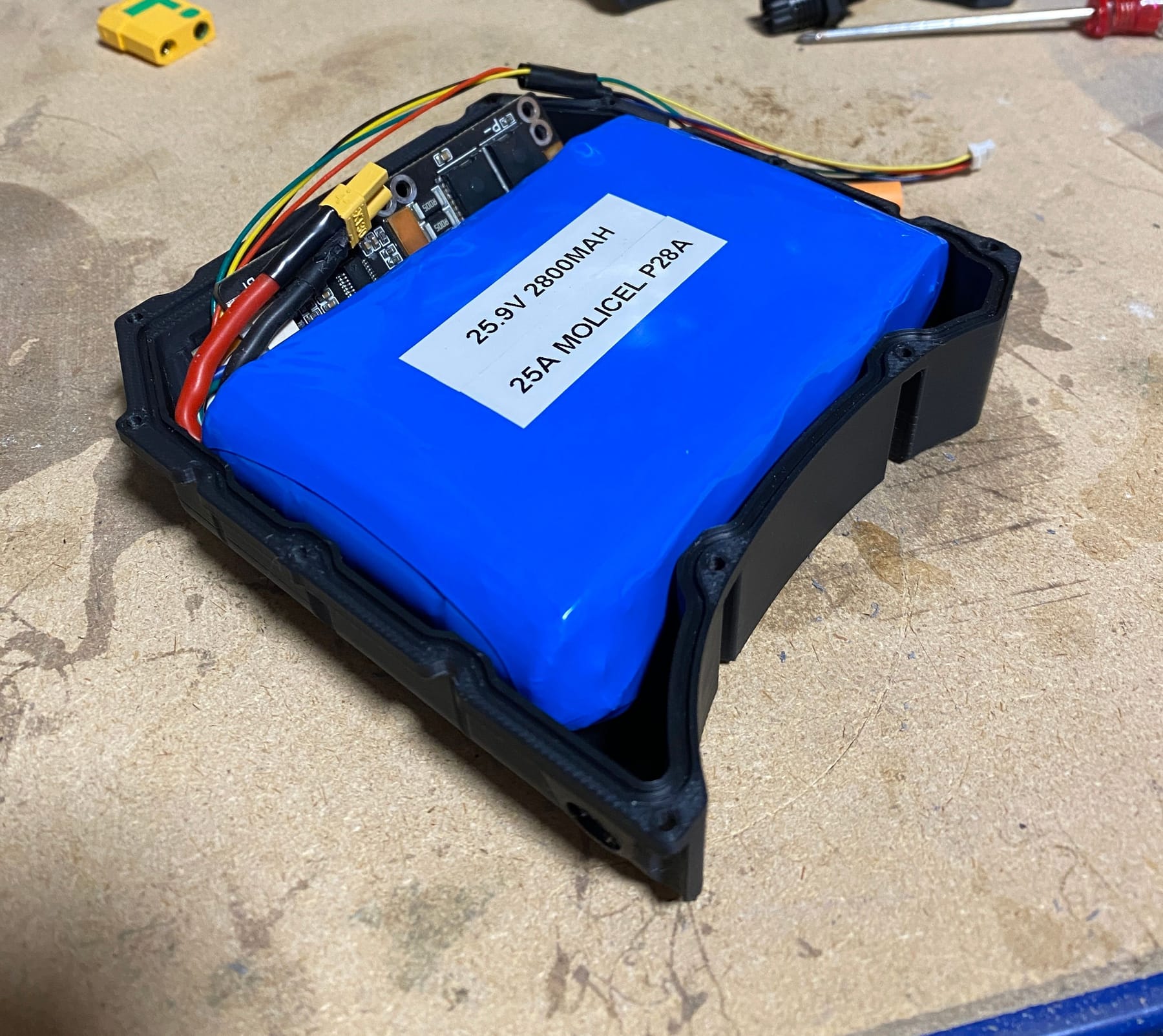
Balance leads were a bit thick but I didn't want to re-crimp and pin the header so used the one that came with the BMS and used a little bit of hotsnot to hold it in place before putting the blue goodness around the pack.
I don't know why but the pack just feels unsafe until the blue stuff is wrapped around it. Before I'd tentatively pick it up but now I'll throw and twirl it about without a care. Might say more about me personally. Out of sight out of mind... definitely out of my mind!
I still needed some stuff to make the harness so I instead moved to cutting the motor cable to length. Risky step and I don't like it. Too much cut off and it won't reach. Too much and you have to do it again >.> But I managed to nail it so we good 🥰
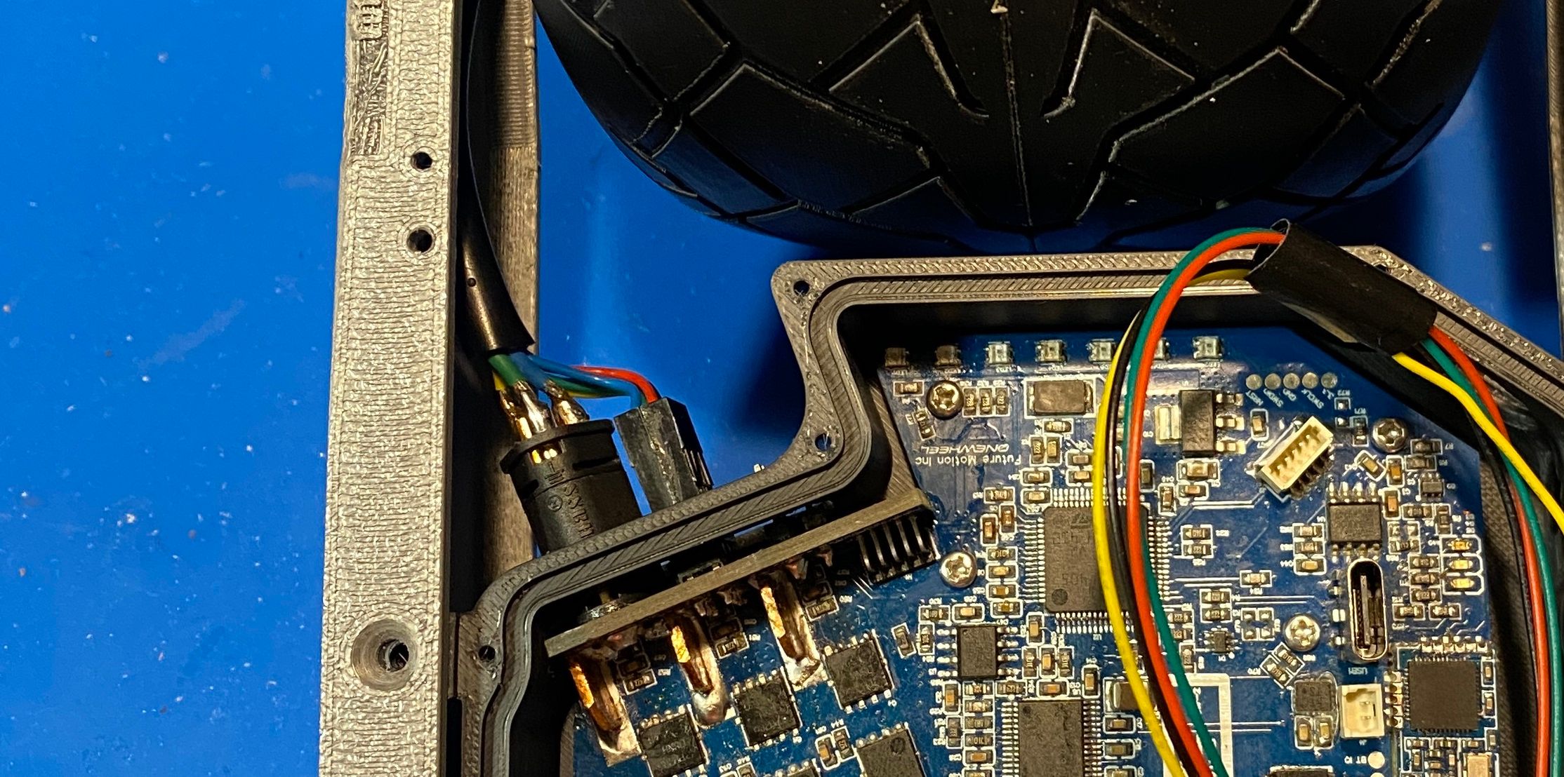
However when I went to test it I got an error I wasn't expecting. Apparently phase 3 was drawing current no matter what the board was doing.
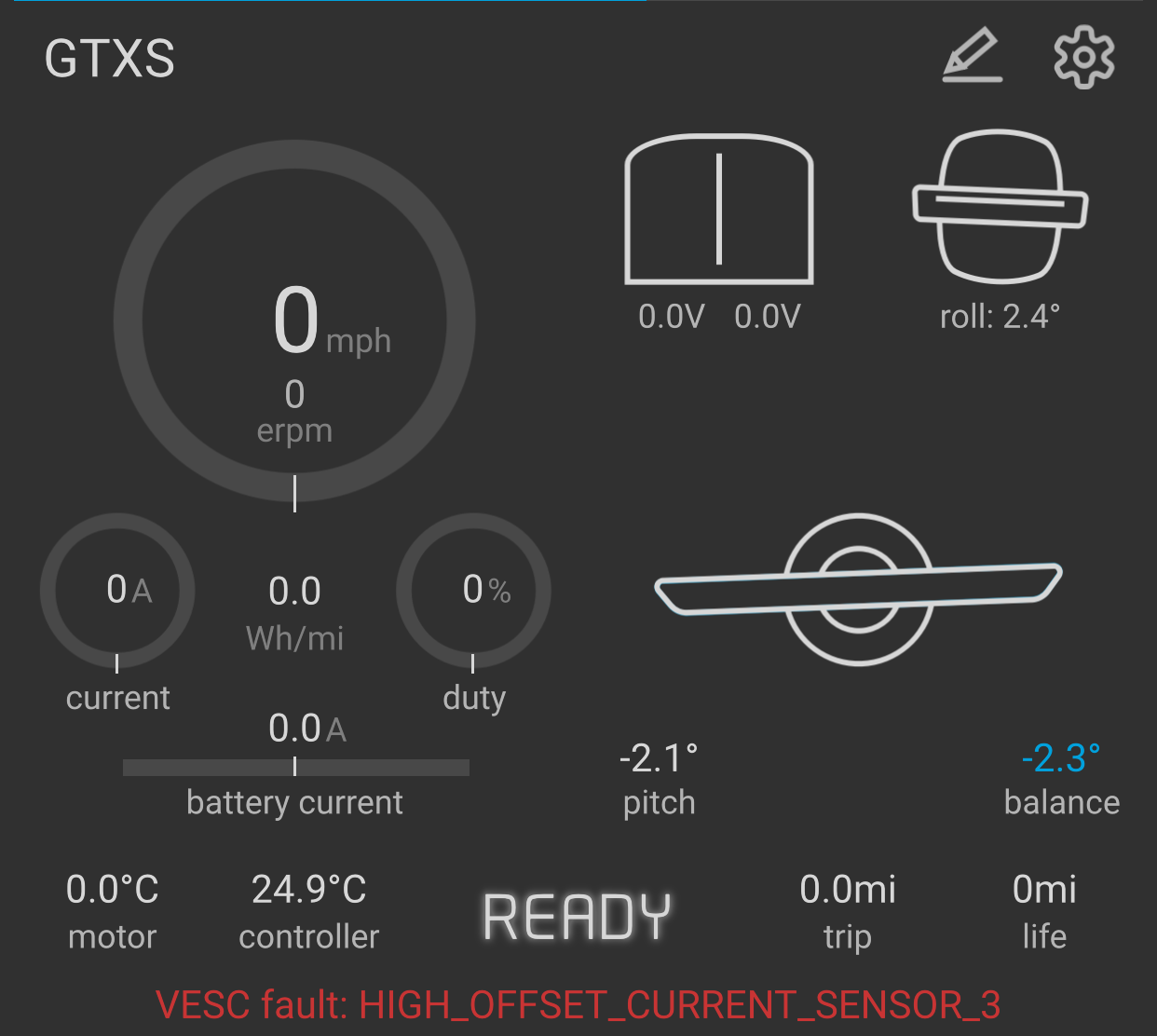
Long story short Phase 3 doesn't get monitored by the DRV chip but instead via U3. This appeared to have cooked itself so if you have a cheap foccer 2 and get HIGH_OFFSET_CURRENT_SENSOR_3 remove U3 and replace it. Funnily enough Nick also had this happen to a VESC he was using and the same fix was needed so seems to be a common enough fault.
No more fault light and a happy lil VESC. Didn't bother recording it spinning as it's the same as previous and I needed my phone to control it and record so wasn't gonna happen. Just have to trust me it works 😊
-
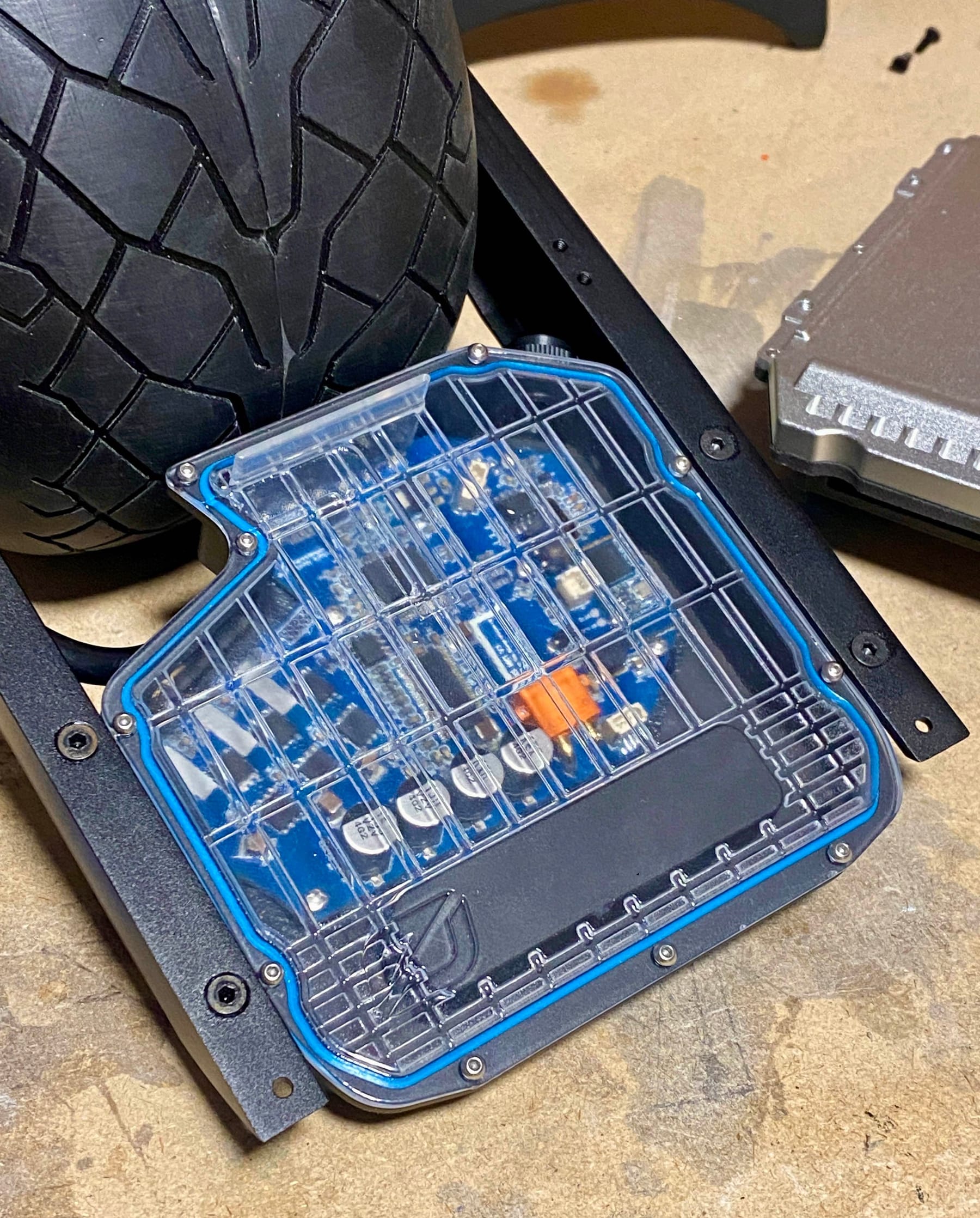
Next challenge was making the controller lid. I wasn't sure if I wanted to resin print it, resin cast it or pay to have it CNC'd out of polycarbonate. Since the former is easiest and the latter the hardest and more expensive I decided to give it a shot. My curing station looks like I'm up to some evil shenanigans so enjoy a picture of that.
I won't bore you with the early prototypes and failures with me snapping one in half because I overcooked it with the print settings. Instead here's pretty happy final versions
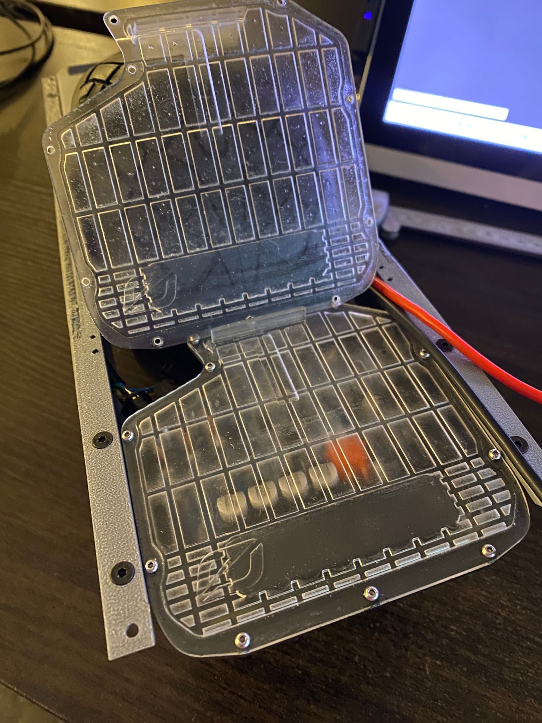
Bottom one is the new one. Seems counter intuitive at first but printing with all the nasty support on the flat nice side allows you to easily sand down the surface and get a suuuuuper smooth finish. 1000 grit final and a light buff with some clear coat made it pop.I still need to work on the gaskets and I had a dilema. Do the stock black one that's kinda boring and keep it vanilla ooooor use a much more thematically coloured TFL gasket. I put a poll out on Insta and the results spoke for themselves.
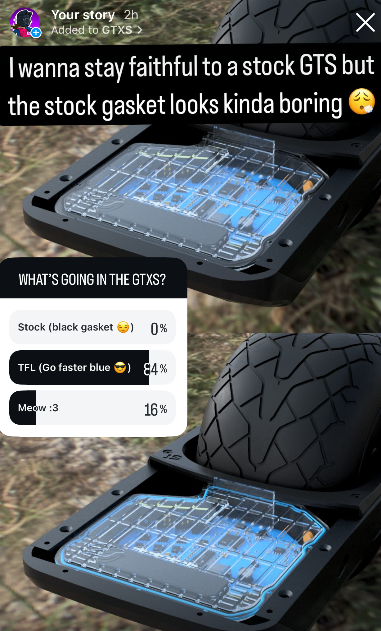
So guess I'll be making go faster blue gaskets when I get the material and dye.
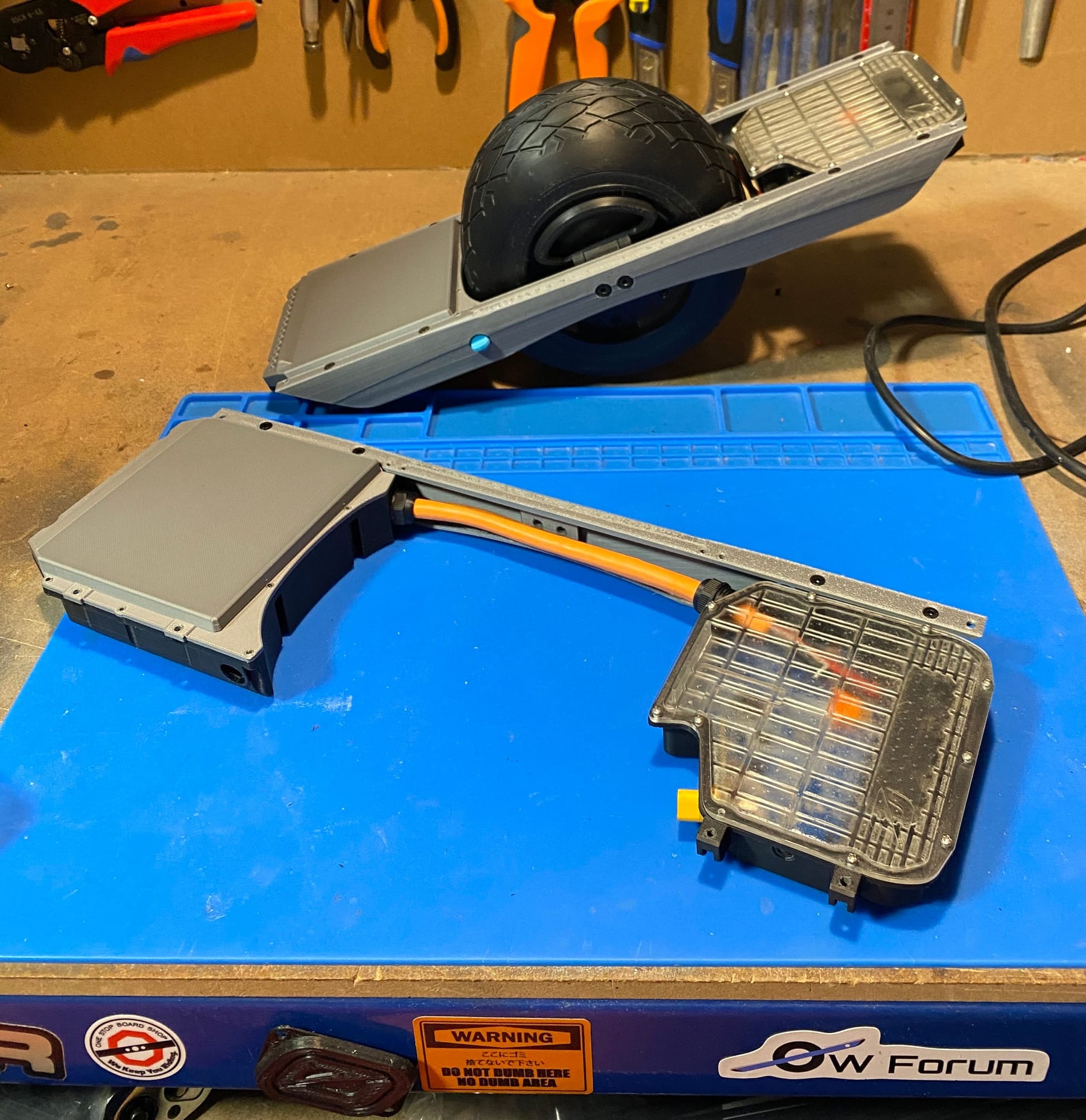
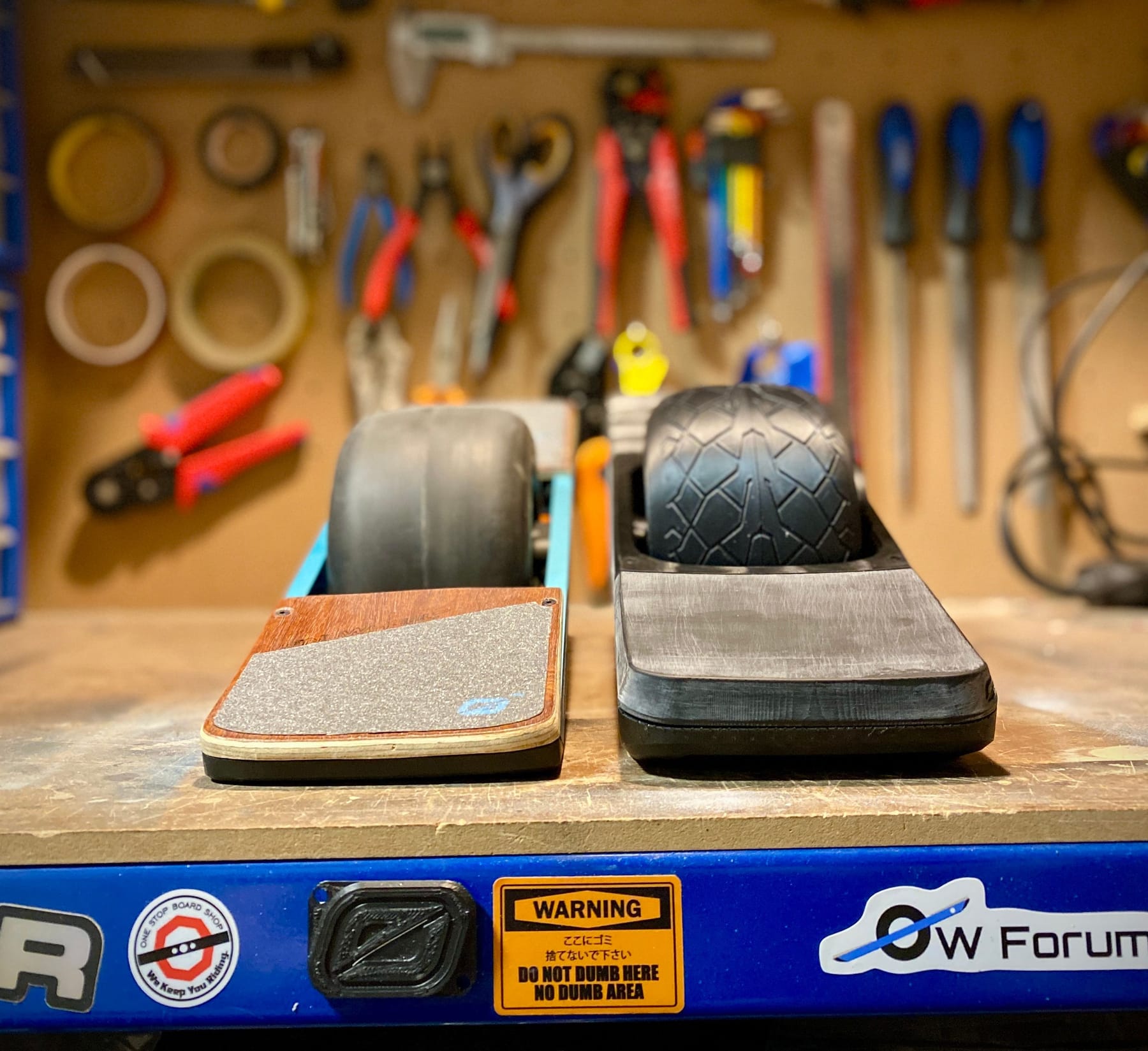
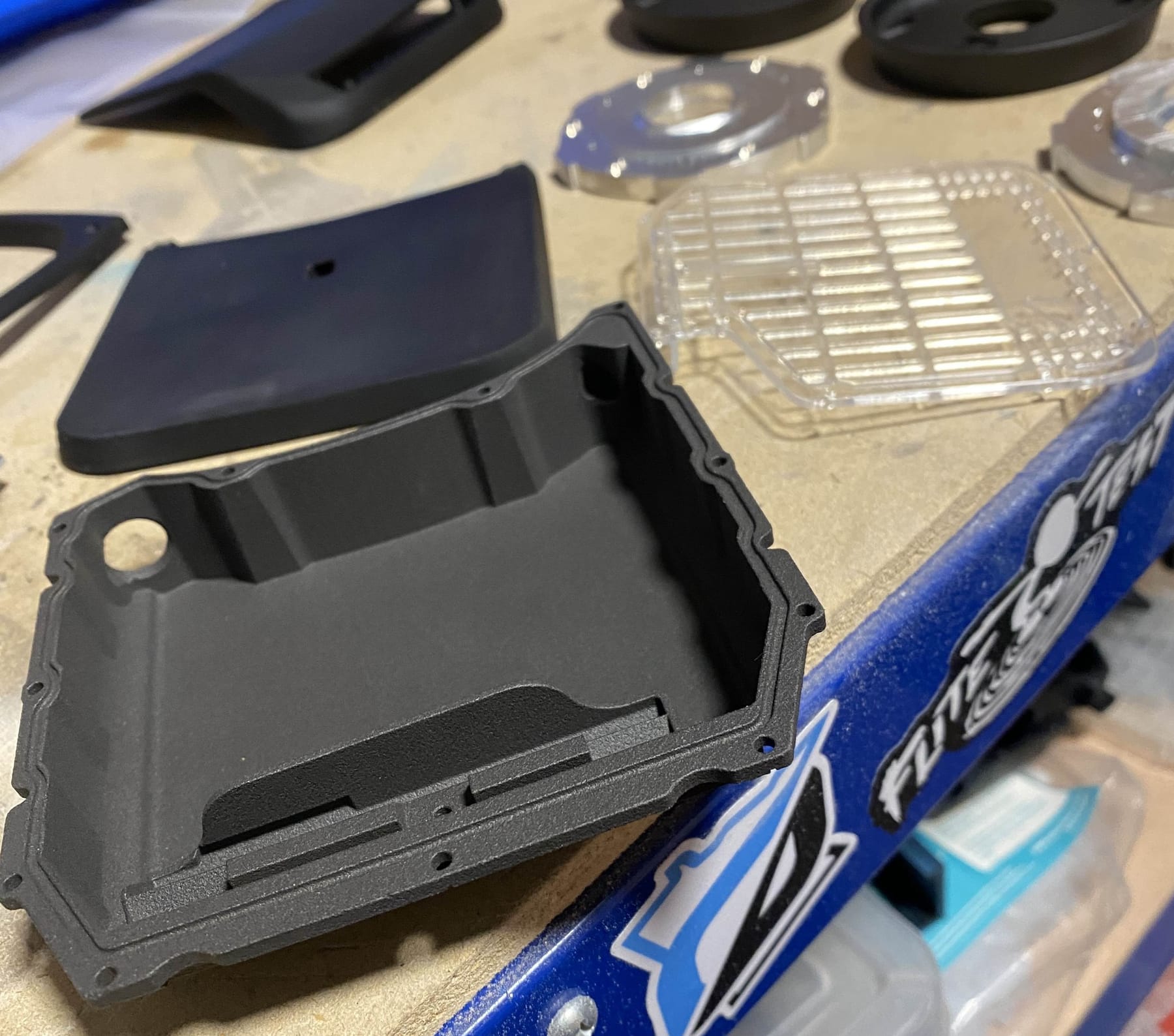
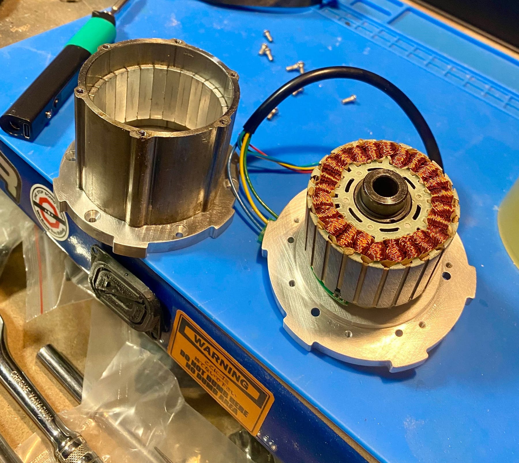
Meanwhile a little care package came in the post. Thanks to the legend himself Radim Klaska for sending me a GT controller, BMS and a pint controller for some future devious plans. Using them side by side with the GTXS you can kinda see how similar I managed to get them.
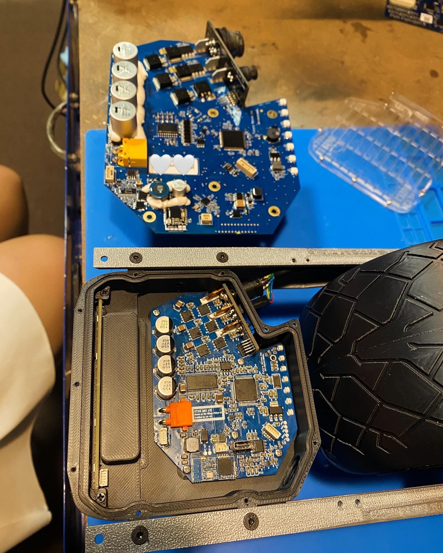
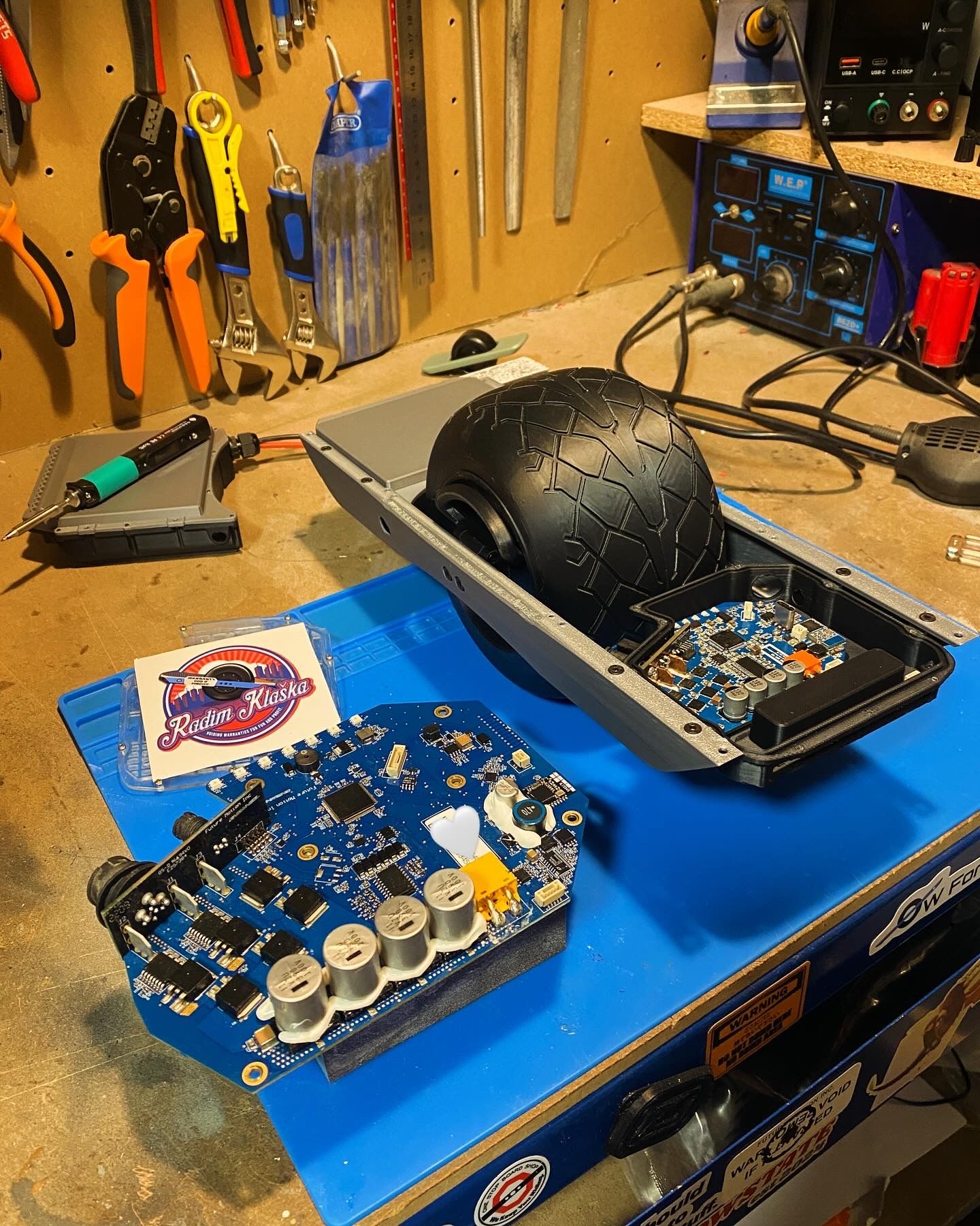
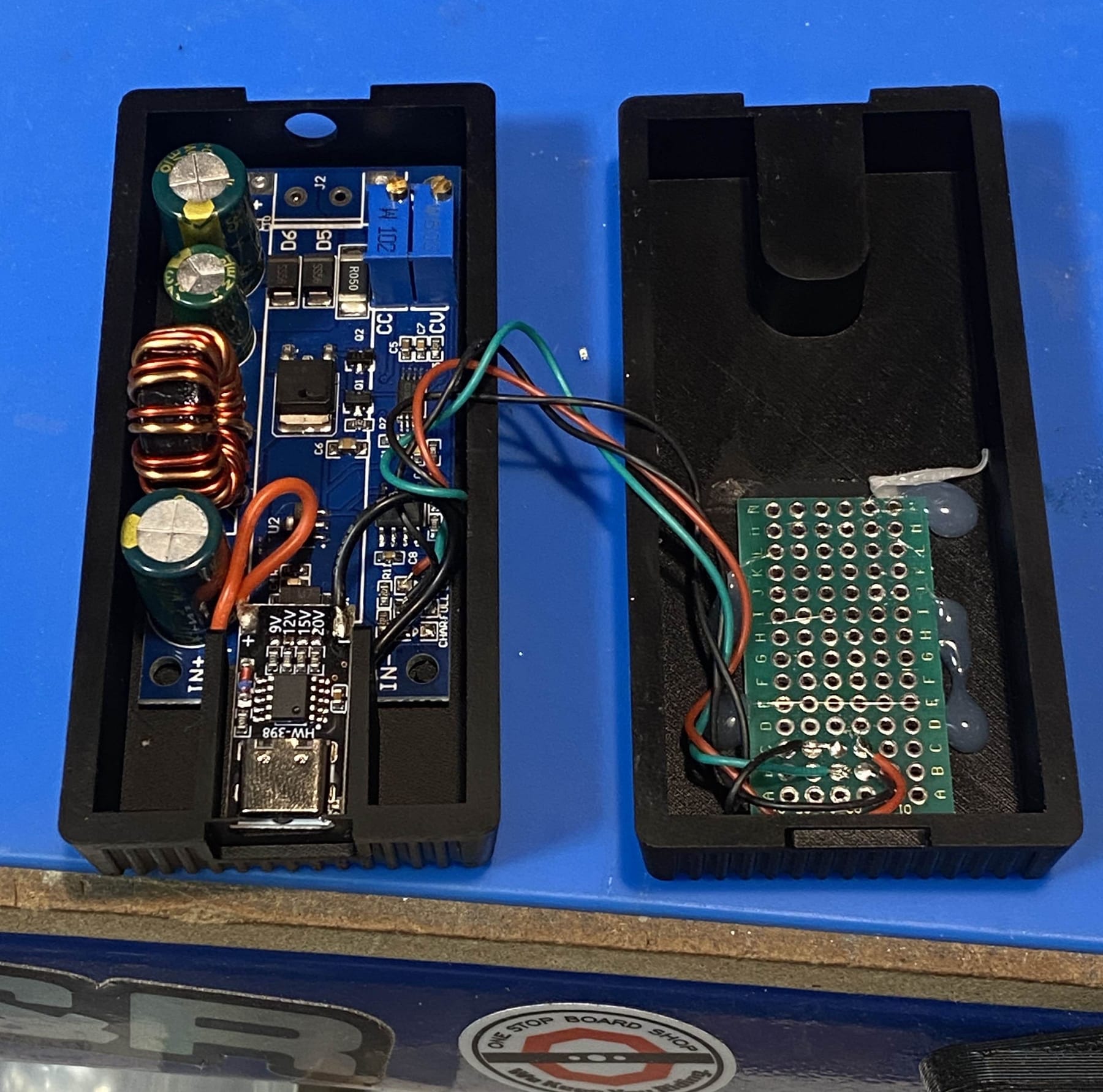
I'll be pulling it apart to reverse engineer a custom controller and get a schematic out of it for some experiments I have planned. However here it serves well to demonstrate scale 😊Back to the main goal again. The board won't do much if I don't get a charger made for it so with callipers at the ready I managed to replicate a brick and cram some magic smoke inside. I'm using a USB PD module to take in power and request 20v. Then a CC-CV boost converter to take the 20v and send a set current into the board until it gets near 29.4v where it'll hold that voltage to top off the cells. Basically how any normal lithium charger works that's not complete trash.
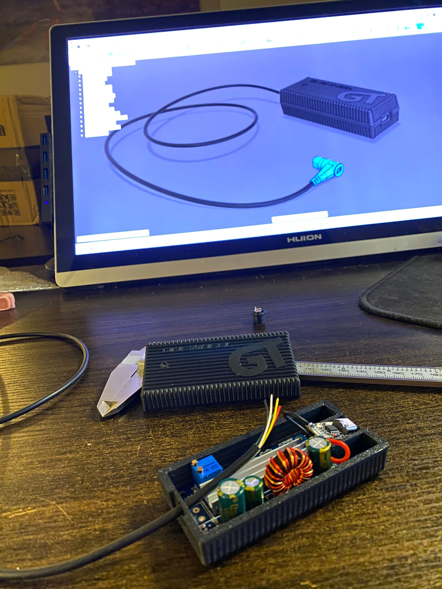
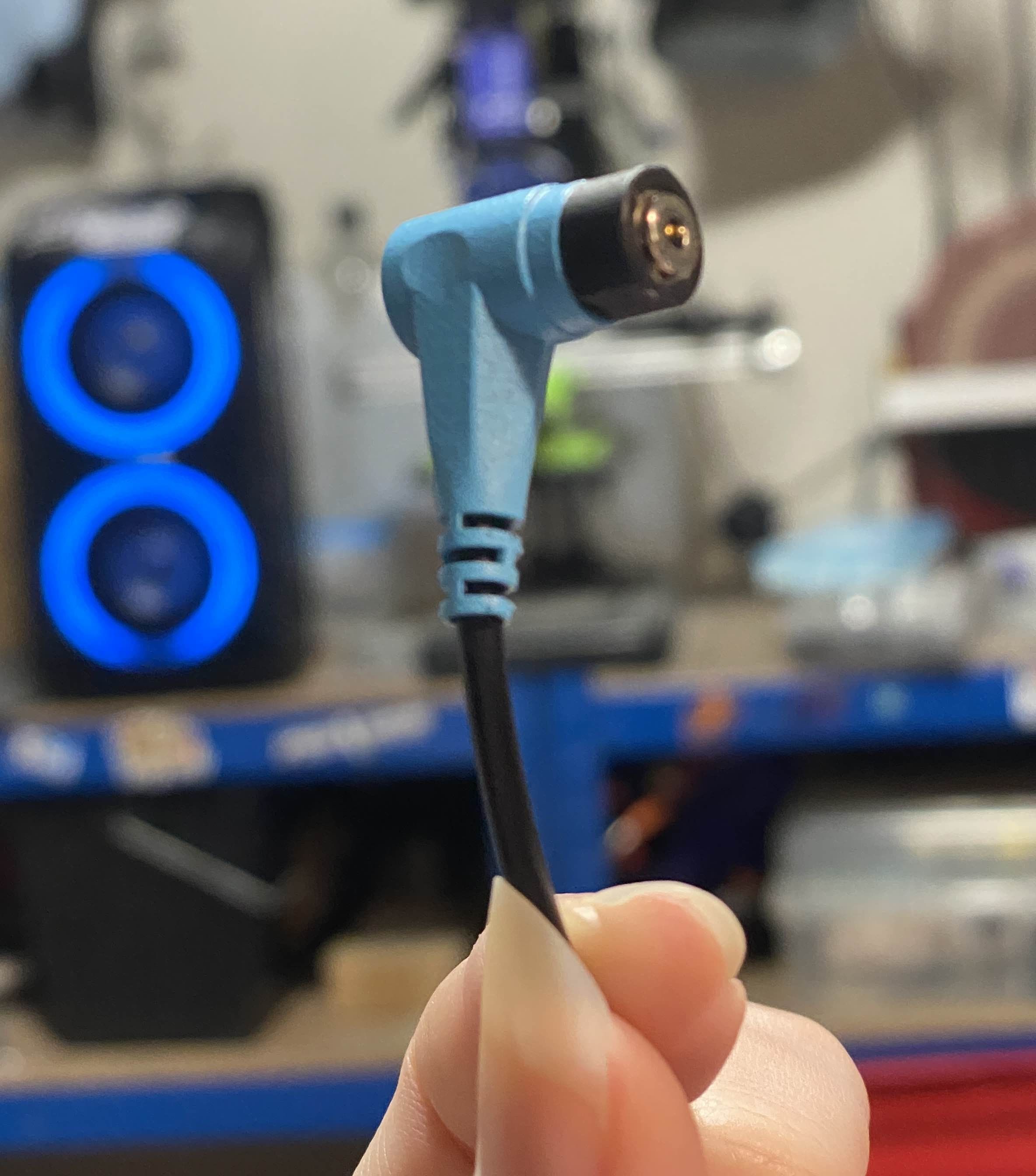
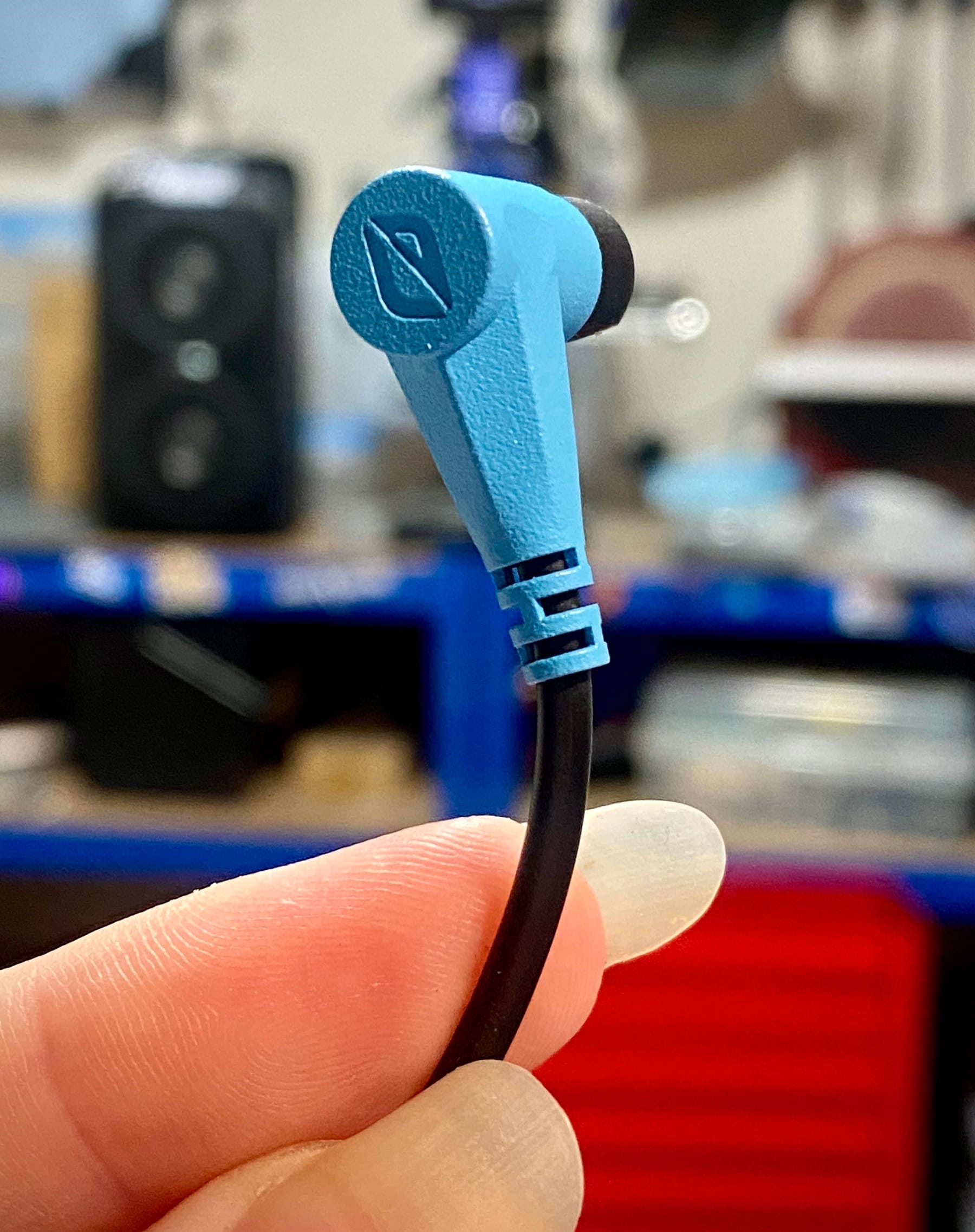
For the charge port itself I'm using some magnetic pogo pin connectors. They work really well and despite being 6mm in diameter this one can do 2amps. Added bonus is they're super satisfying to snap in. It's like magsafe for Onewheels (for ants)
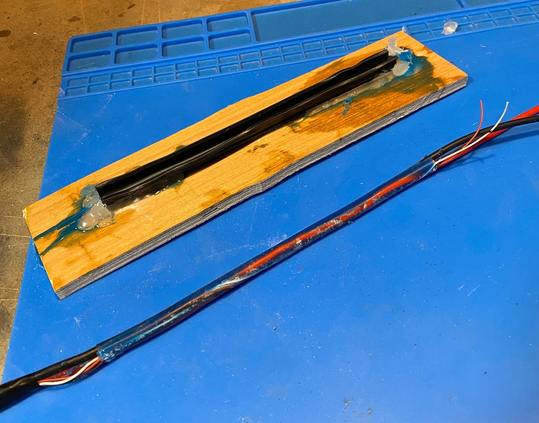
Will come back to this when I resin print the final parts for the plug and charge brick. In the meantime I needed to figure out the harness. I wanted it to be orange like the GTS but finding multicore cable with 2x14awg + 3x24awg wire inside less than 8mm in diameter was a bit of a stretch so I came up with a solution.
Use a mould to encase the wires taught and in position then pour a flexible silicone over. Once cured demould and use heat shrink to get a uniformly round and flexible cable. Heat shrink alone will be weird and kinky. as it conforms to the wires inside and be less durable. I did a test piece first with some offcuts and despite being very messy it worked!
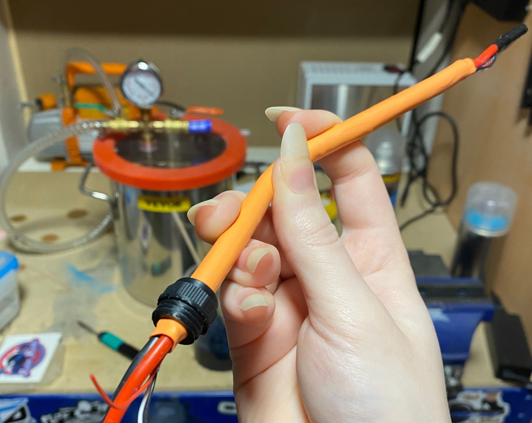
You can also see I made my own glands. The existing ones on the market just didn't scale right and the fitment was poor so a bit of CAD resulted in some functional yet scale looking glands.In an older prototype the cable fits nice and snug. Minor kinks where some silicone hadn't set right or the wiring wasn't taught but overall looks great!
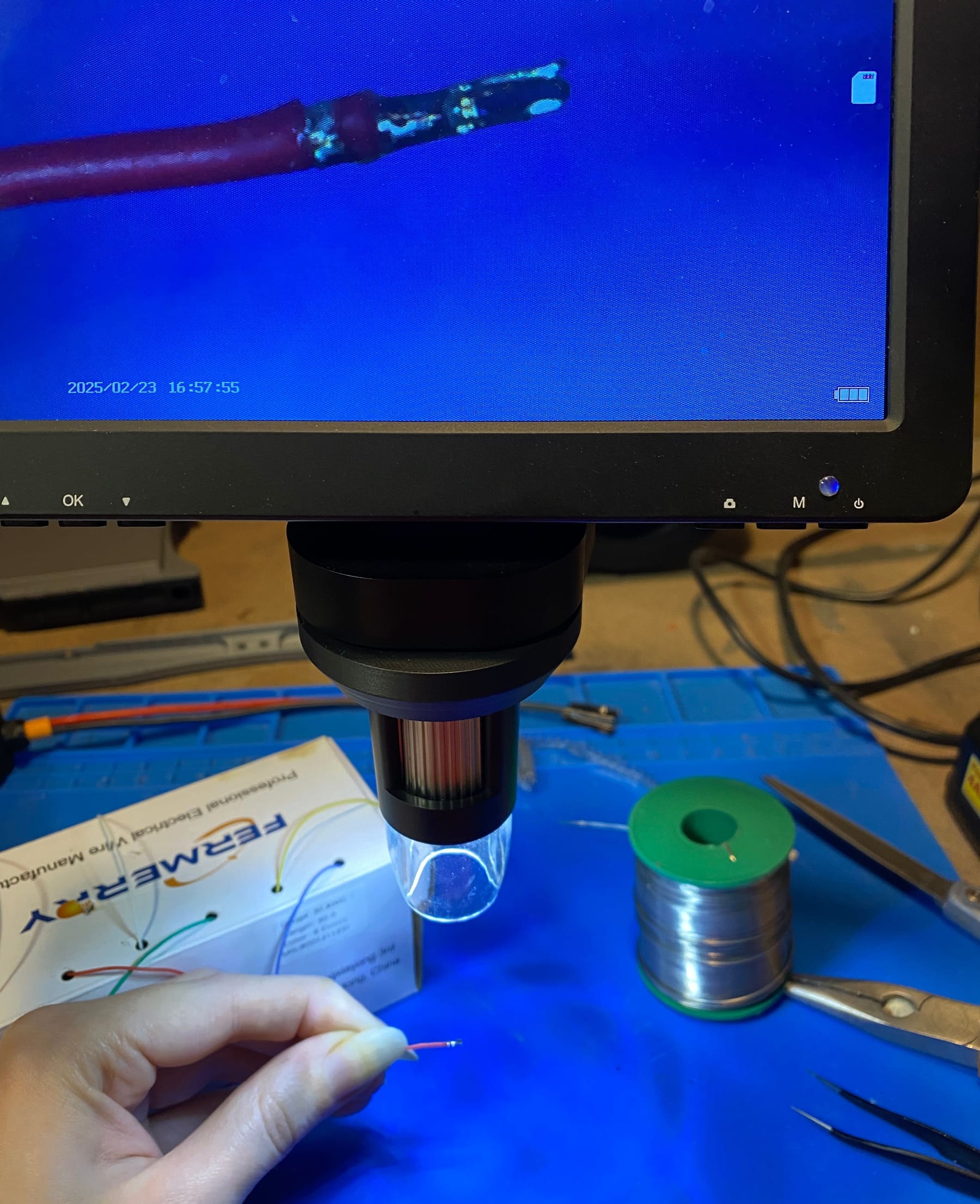
With that being a success it was time to crack on with the final one. I did have to crimp some insanely small connectors for the headlight and battery harness wires. Did these with some tweezers. They are tiny! Here's one under the scope.
I changed the mould a little this time and taught the cables before putting in which helped a lot although made slotting them in a faff. But it all went in well and cast really nicely.
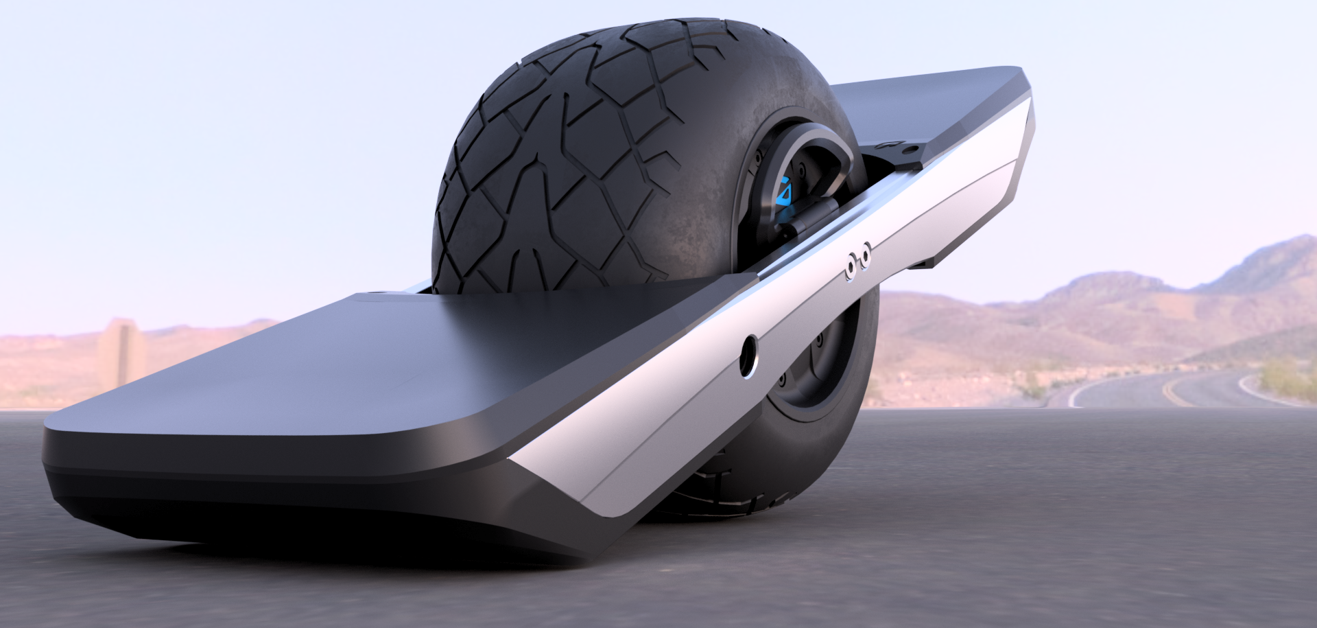
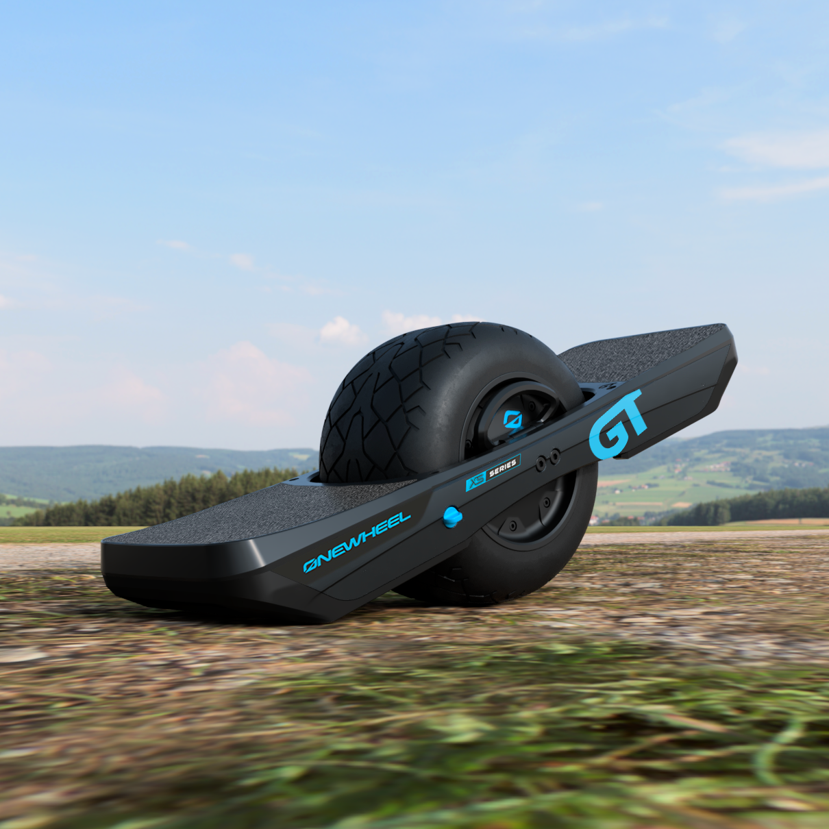
I ran out of time last night to put the headers and connectors on controller side but I'll hopefully do that tonight and share the results of the board running off it's own power 🥰Until then enjoy this render and little pic I took for my application to this years OpenSauce.
-
@lia You are a perfectionist! I can't believe the attention to the smallest detail!
Totally insane! -
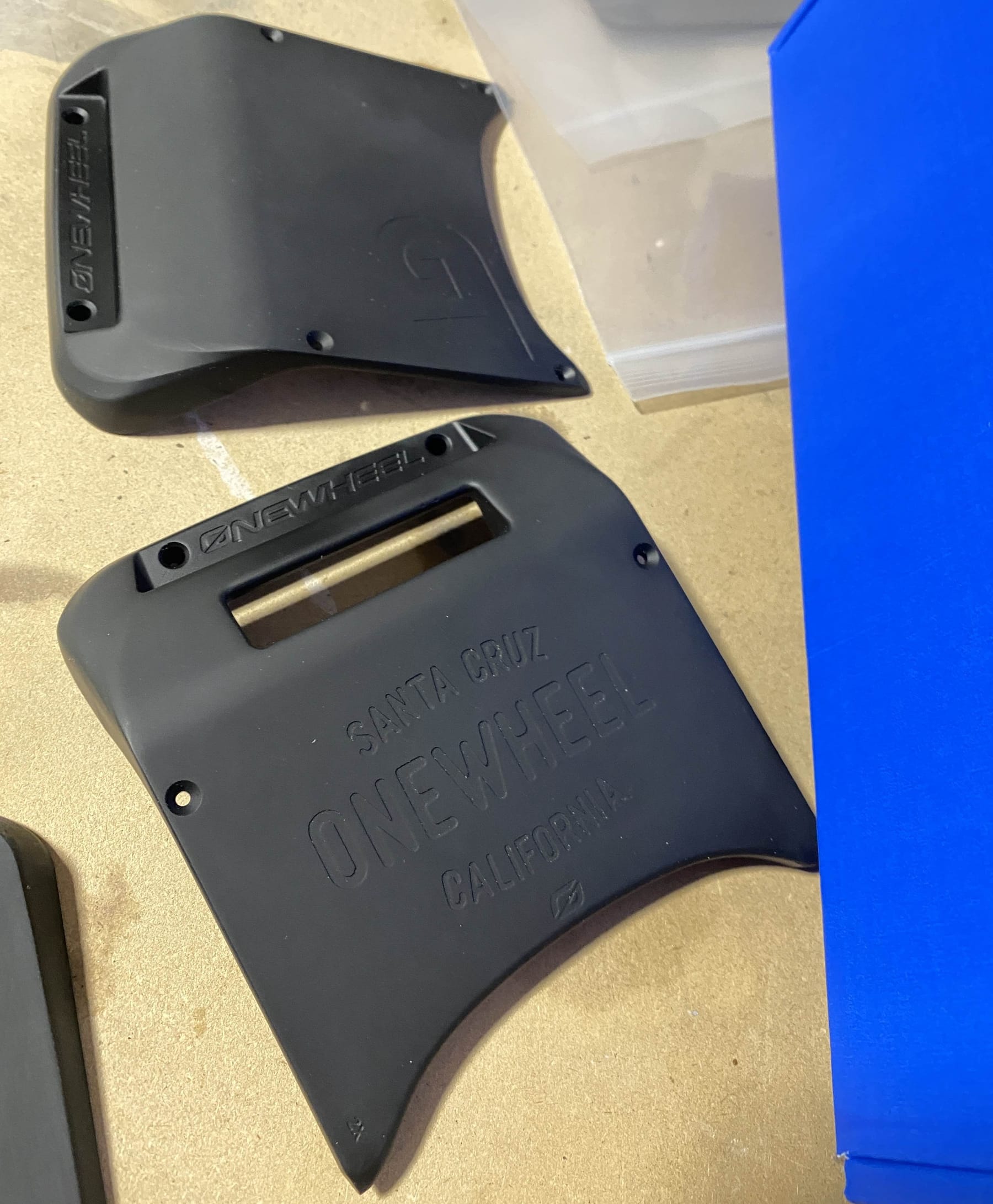
@lemur It's really hard not to 😅 Like I know inside some of the details like the "Destroy Boredom" on the inside of the bumper or the little FM branding on the controller will never be seen by most but it feels good to add it ^-^ Little easter eggs I guess.
-
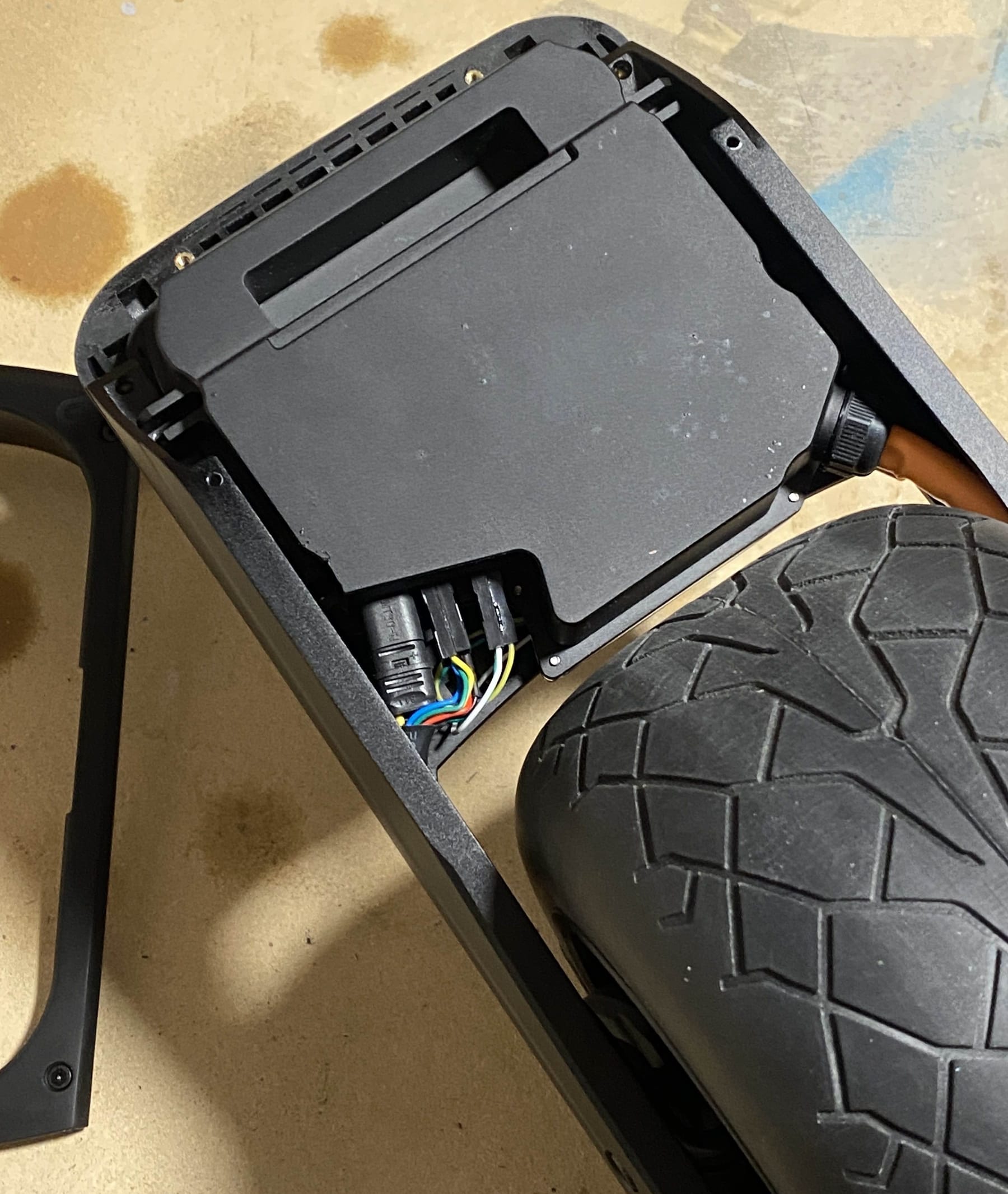
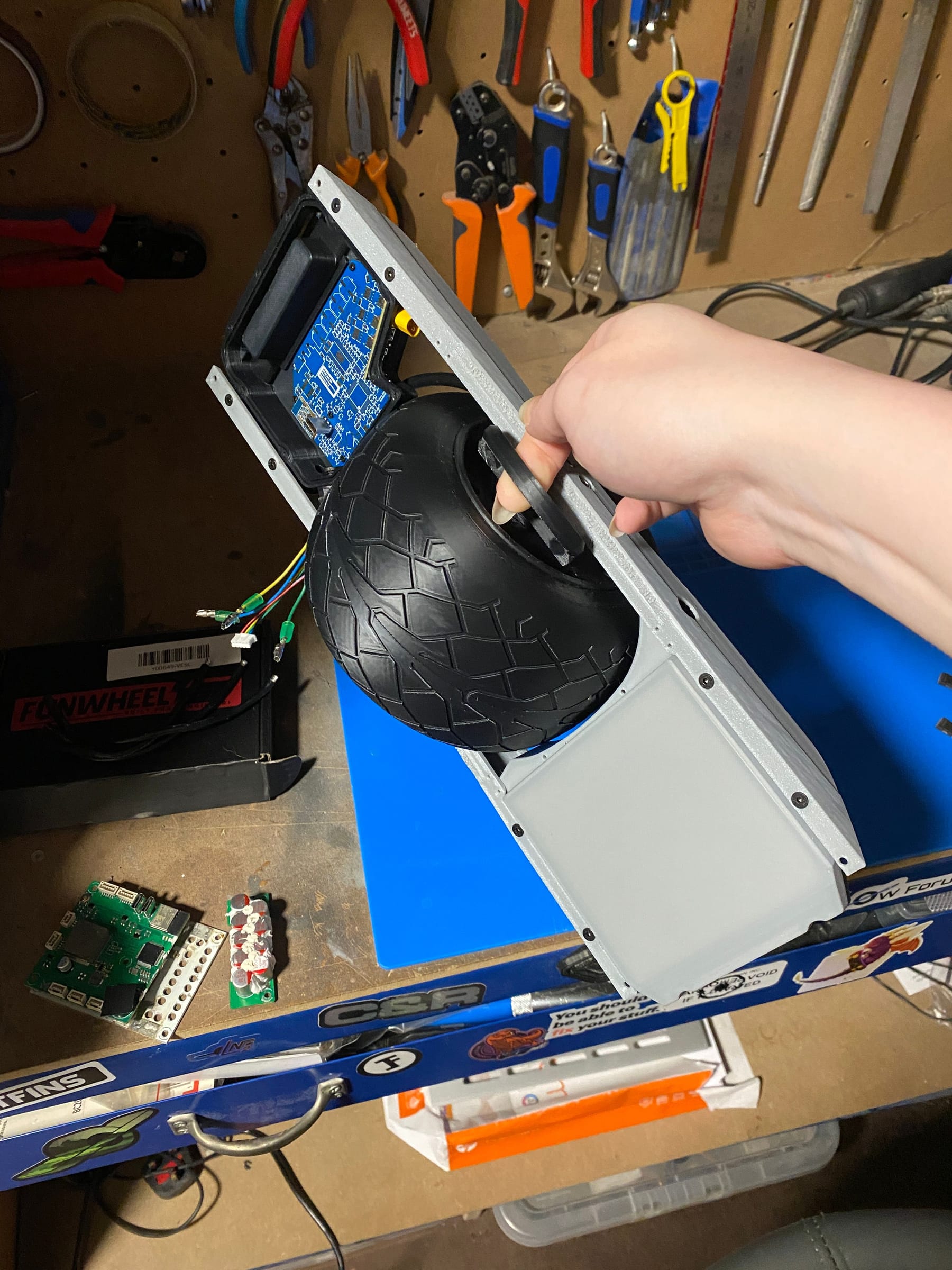
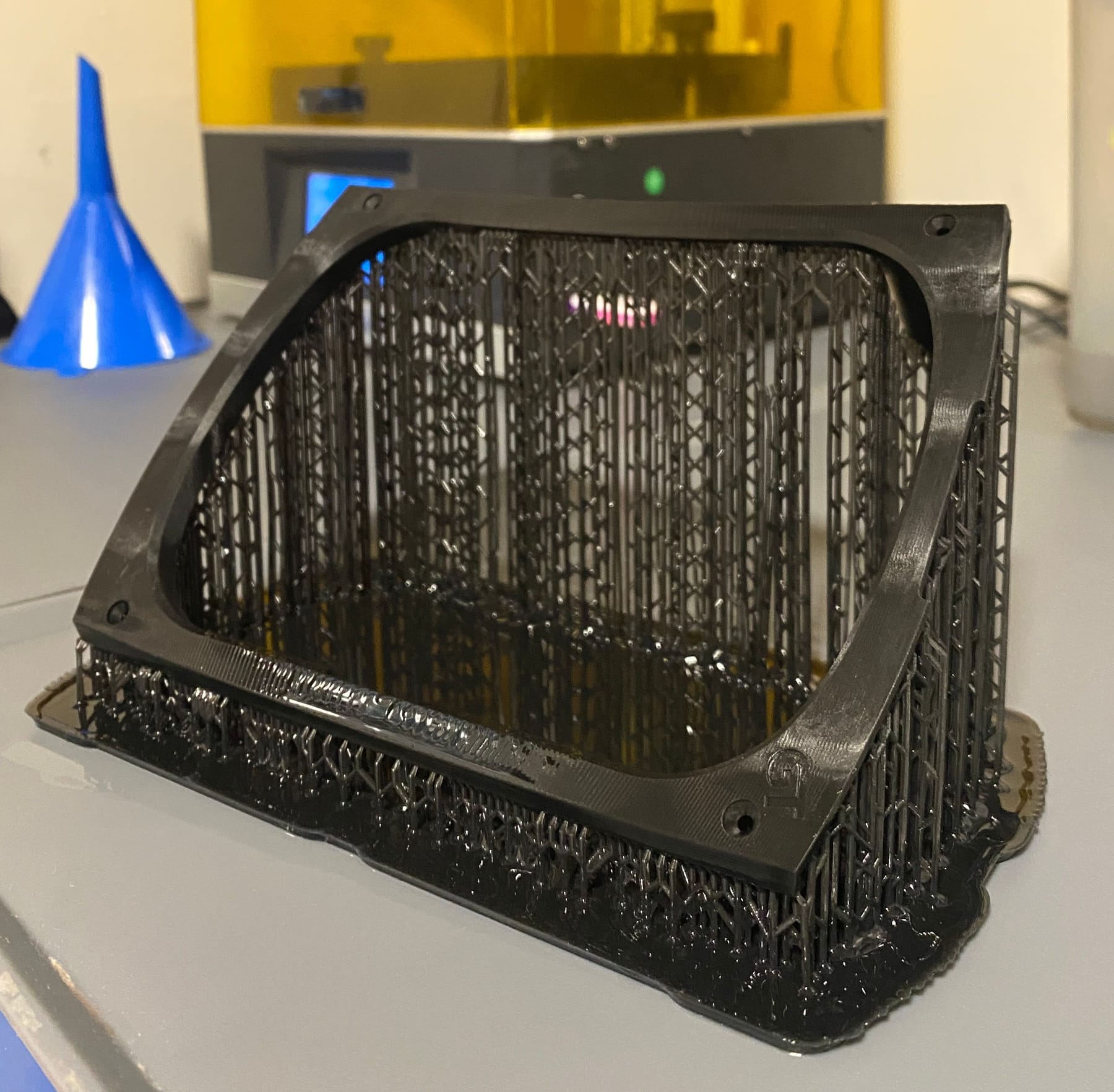
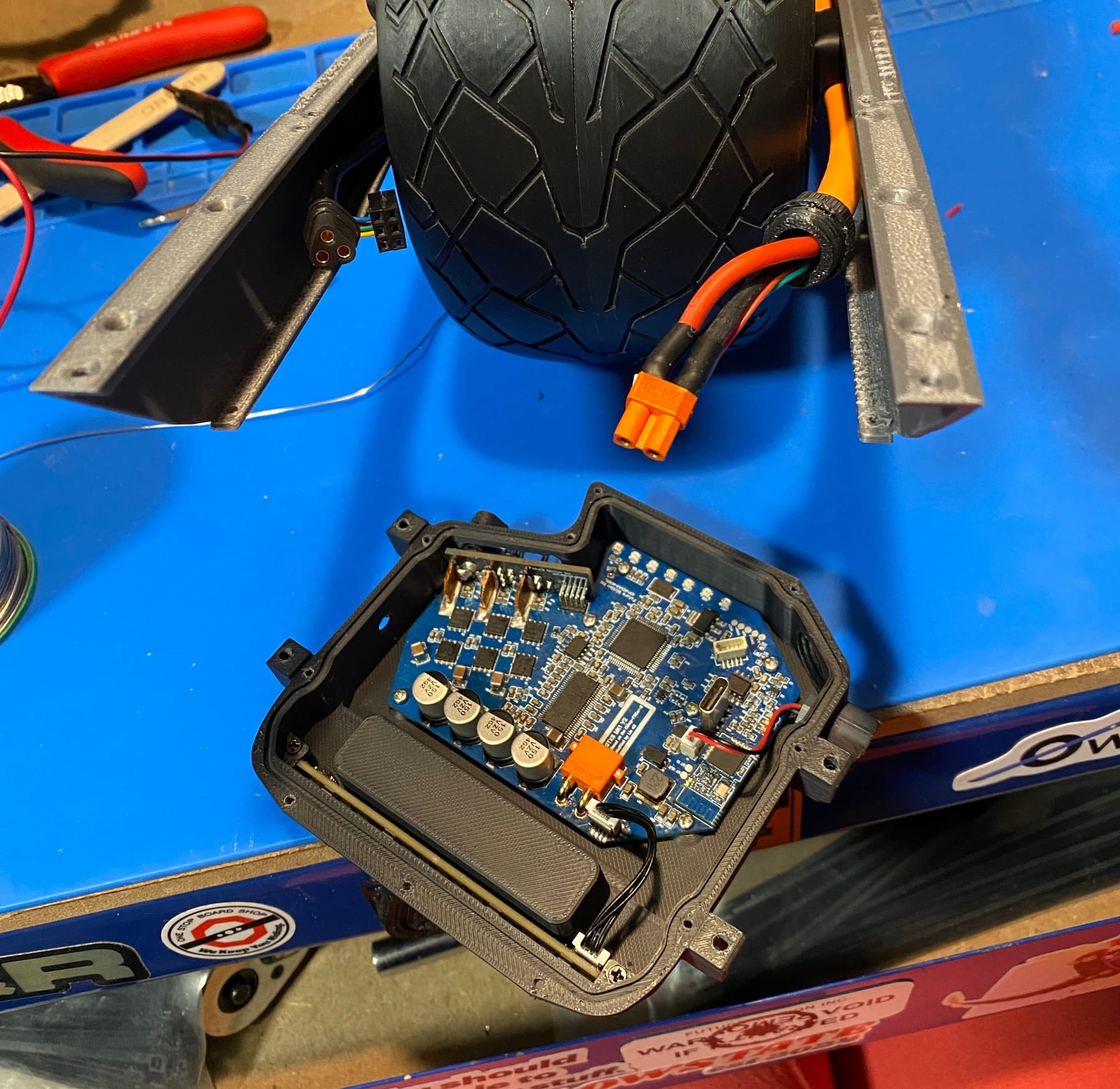
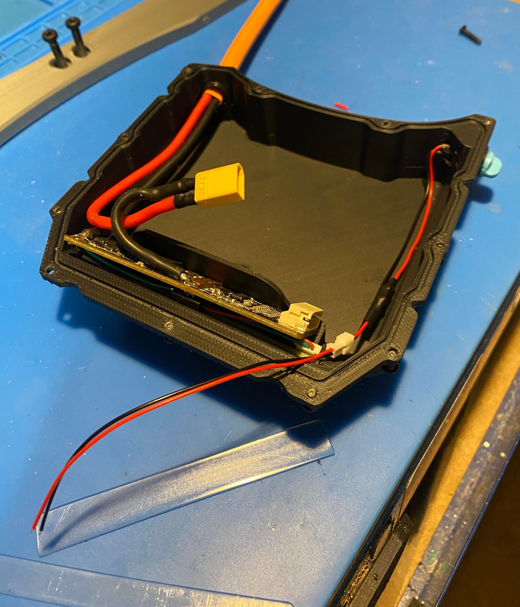
Woke up to some freshly printed parts. One in particular this fender delete. Might possibly be one of the largest prints on the resin machine I've done yet.
After post processing that a little I got the harness headers controller side fit and tested.
Lights in the front and rear all sink up so that's a bonus. No pic of the lights since I was holding wires together but trust me it looked fab. I just need to attach the battery connector now but I forgot I never painted the female end of the xt30. Trouble is painting these is really tedious. Too much and you ruin the finer details. Too little and you see the yellow.
I then remembered you can dye some plastics and would you know it these xt30's are made of nylon (or something very similar) which takes dye easy. A bowl of boiling water, some synthetic dye and about 10 minutes of stirring got me some really nice orange connectors!
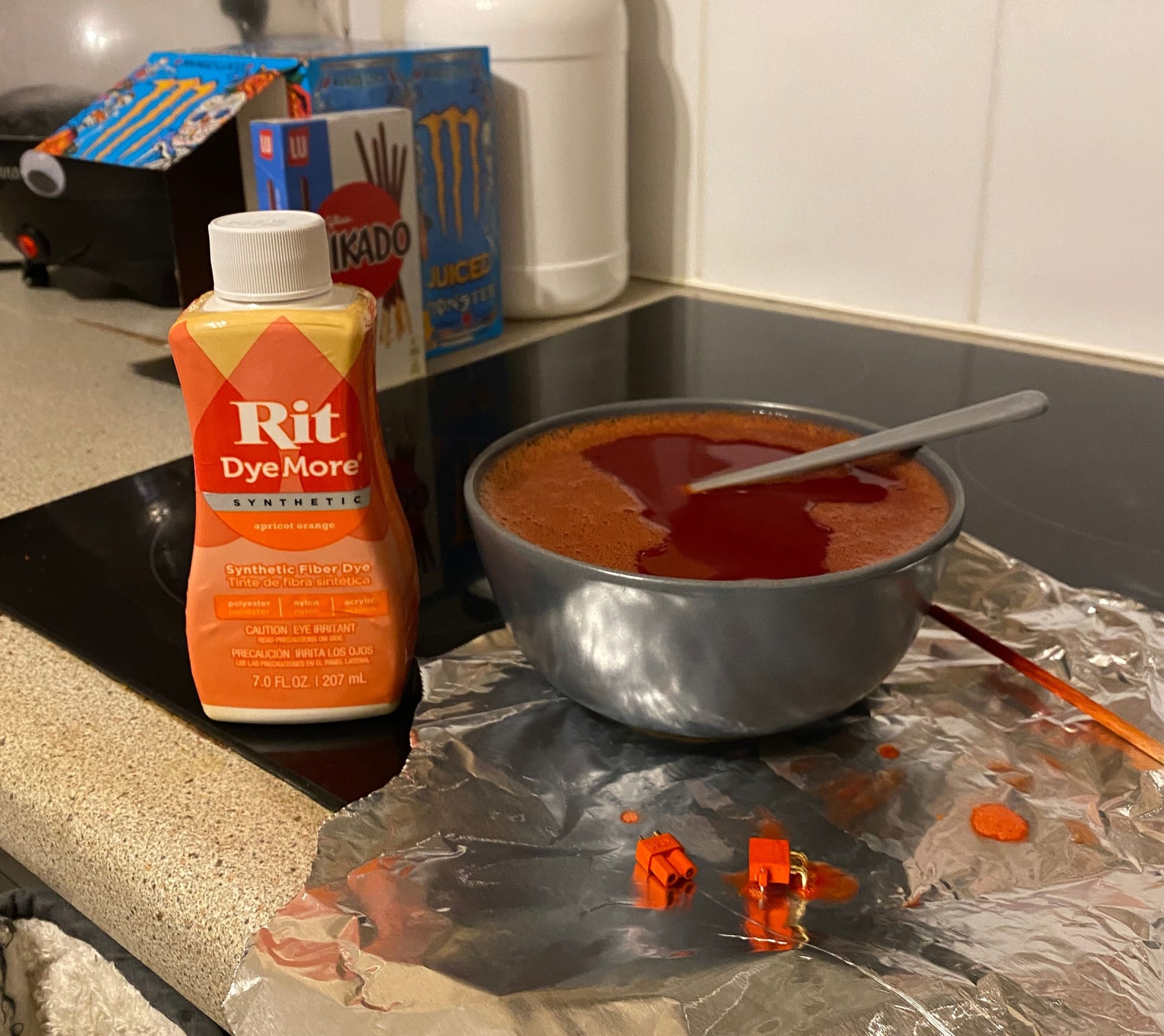
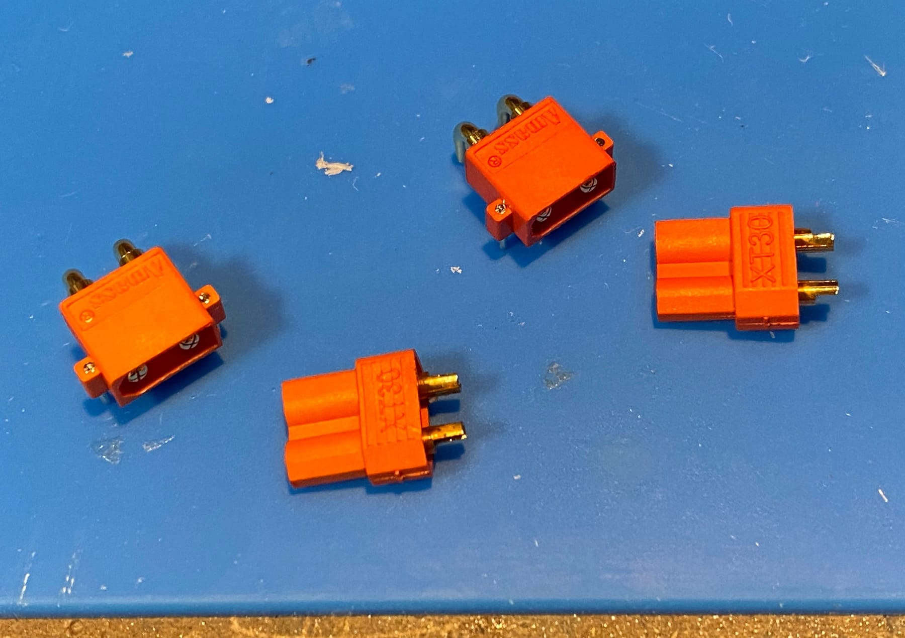
Unlike paint it doesn't scratch off as easy which is a bonus and no more masking the tiny metal bits!
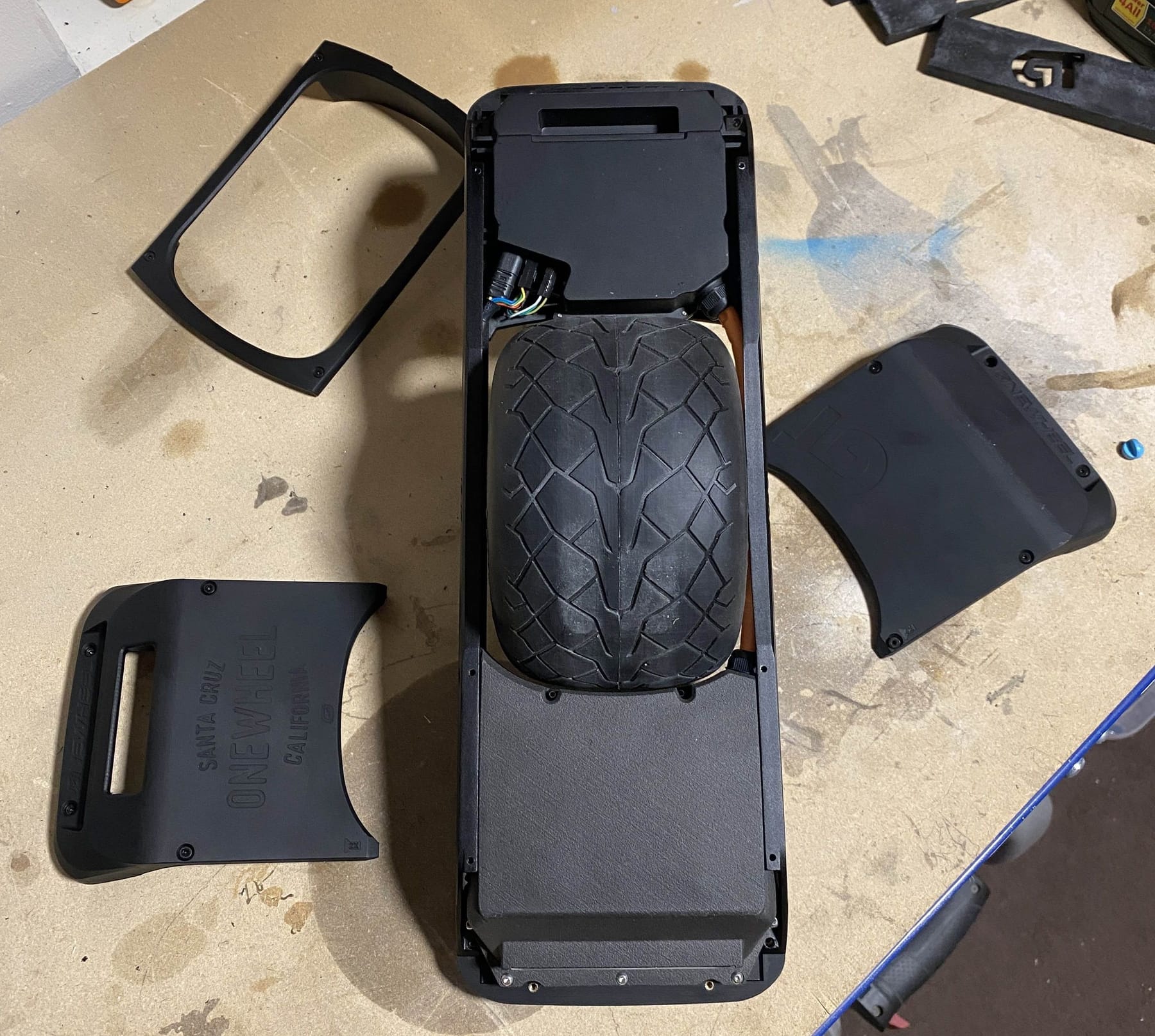
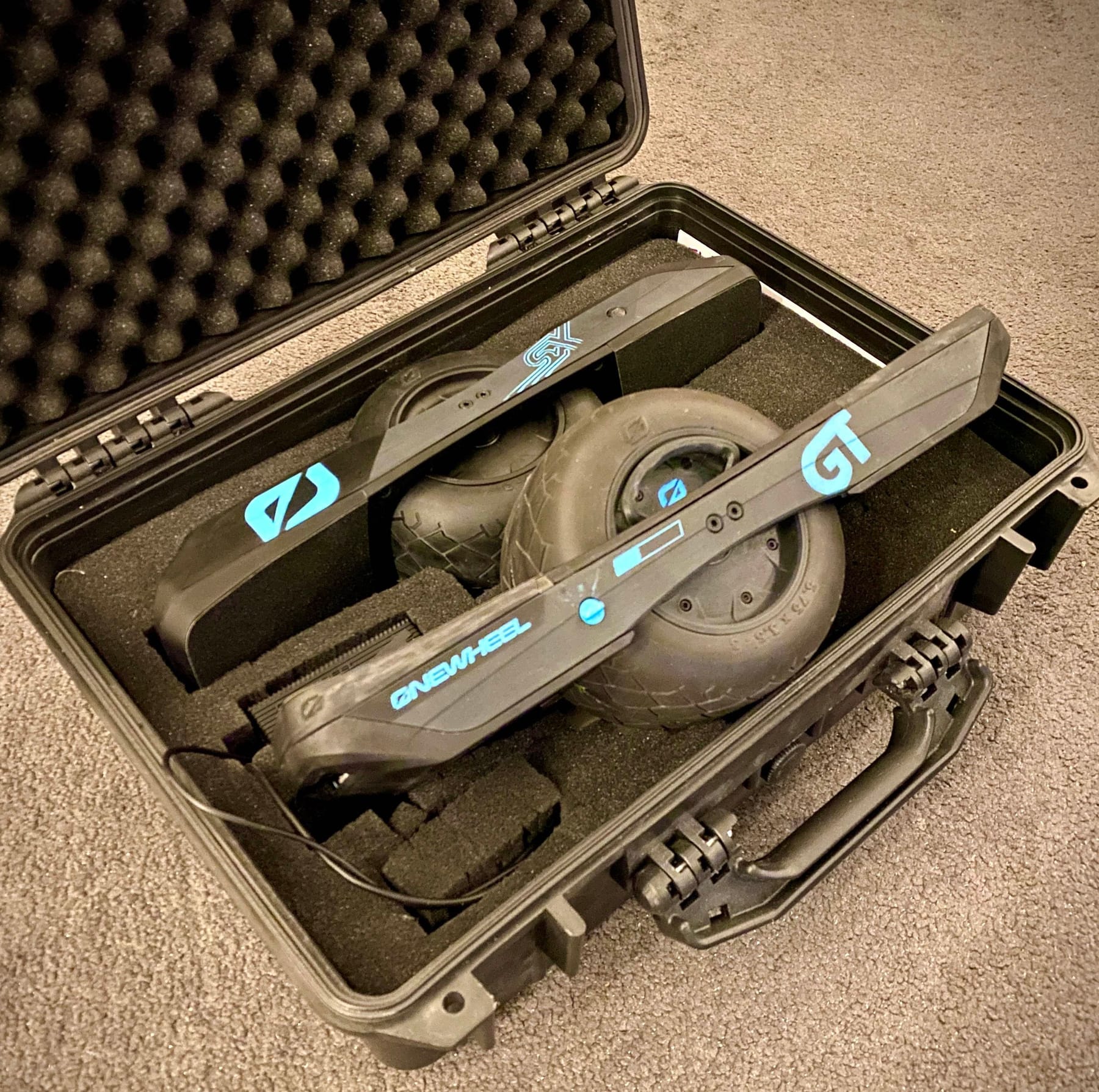
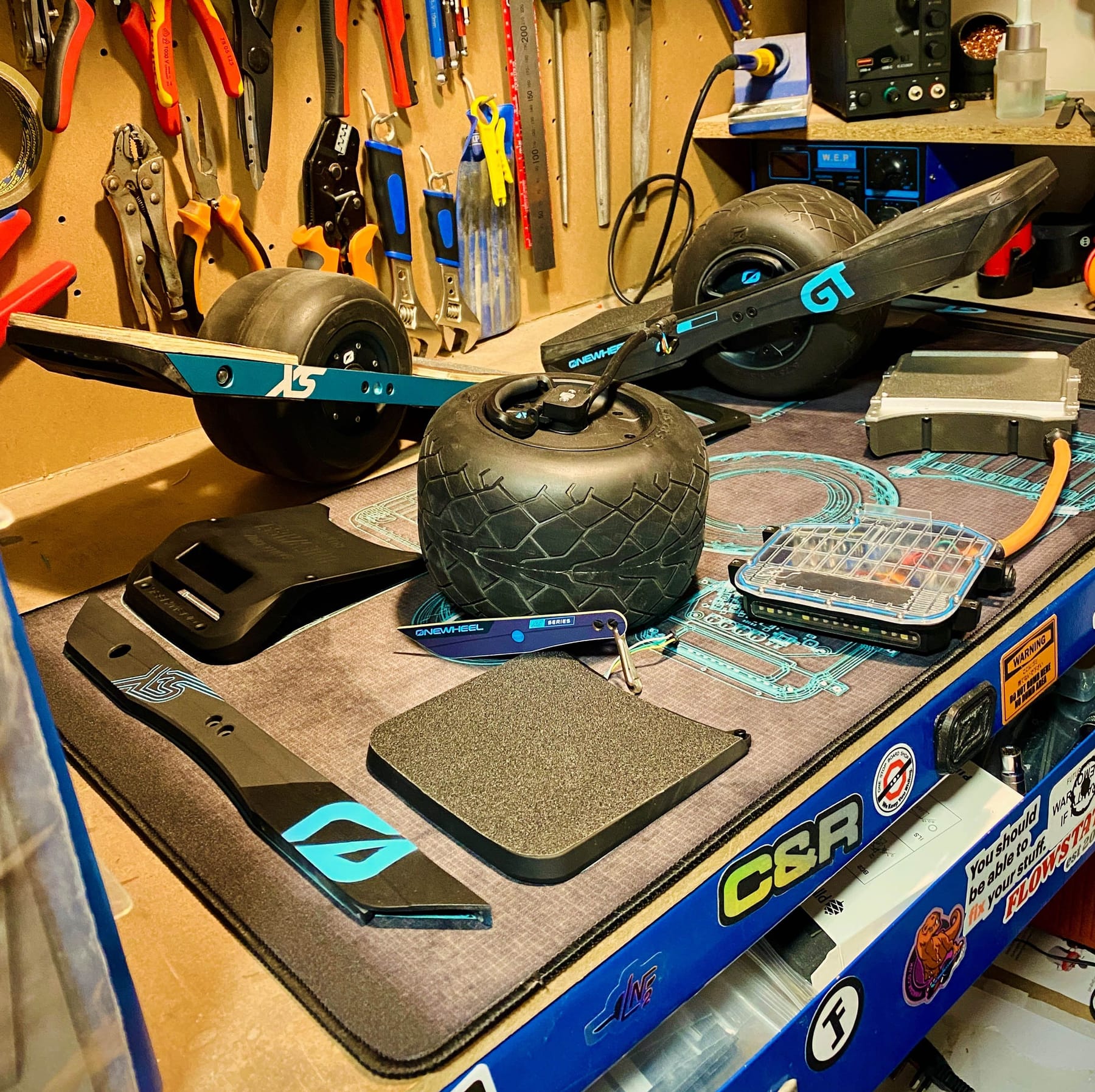
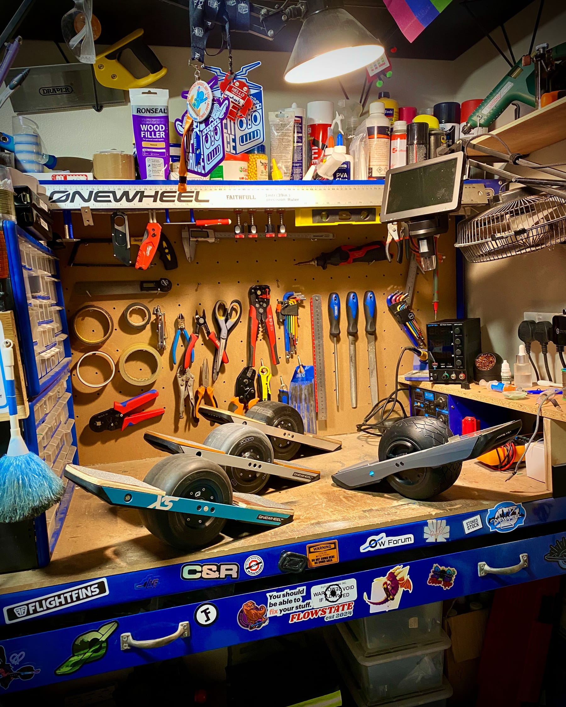
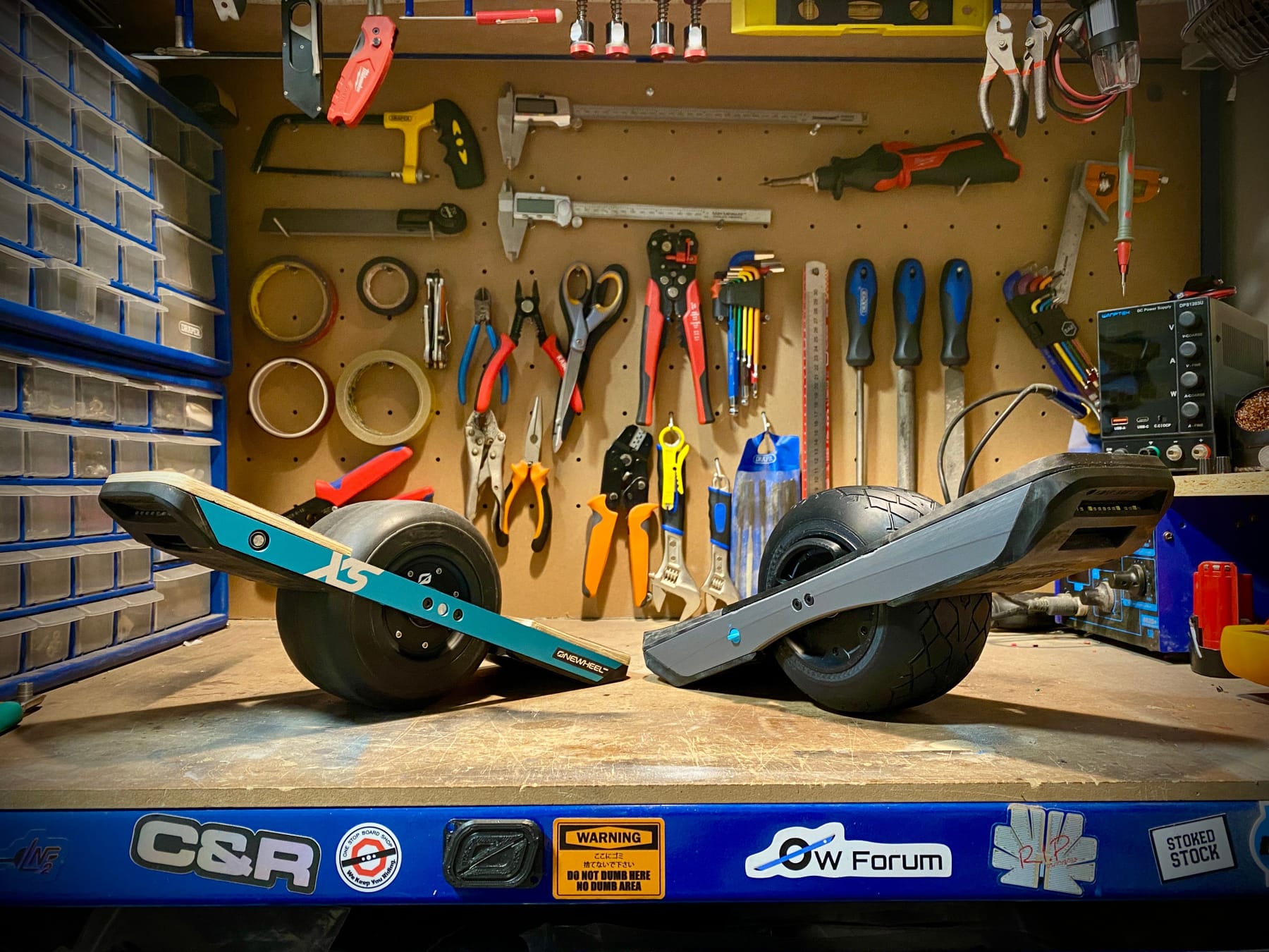
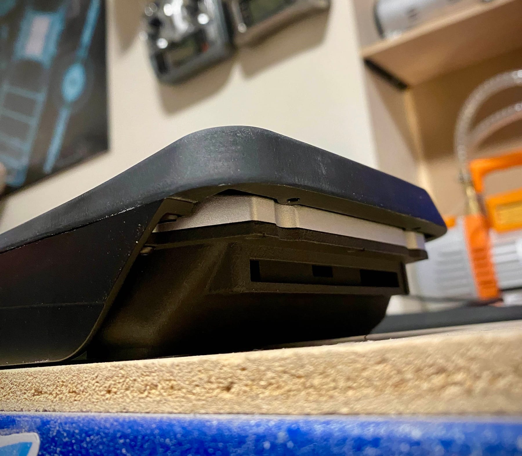
I ran out of time today to fit them so instead I'll leave you with some more cool pics of the XS and prototype GTXS together 🥰
GTXS sporting the new high kick rear pad and the fender delete now.
-
It was finally time to add the XT30 😊 I've been putting this off for a veeeeeeeery long time.
And thankfully without issue (other than be knocking the headlight connector off) it woooooooooooorked!
SHE LIIIIIVES!!!! 🥰🥰🥰🥰🥰🥰🥰🥰
(apologies for the vertical video but sorta filmed it for Insta)I'm so happy it booted up fine. Batteries are a little lower than I thought so after a brief hiatus I'll rig up the charger and get it back to nominal. Unlike the XS I will be able to actually see the battery health too 😅

-
Hiatus over but I'm still a bit slow atm. Health thingy (I'm okay don't worry just recovering still)
Been struggling to figure out a way to stop battery voltage being present at the charge port. A diode is the obvious answer but it introduces a voltage drop which when current is passed will heat up heaps. I could use a fet instead but as the voltage is always present one side I can't easily make a small circuit to block the voltage and turn on when present in the reverse. Giving up I just added an inline smd 3a fuse so if something does go wrong it blows without stopping the board working. That leaves the charge protector to do the heavy lifting keeping the 29.4v from escaping.
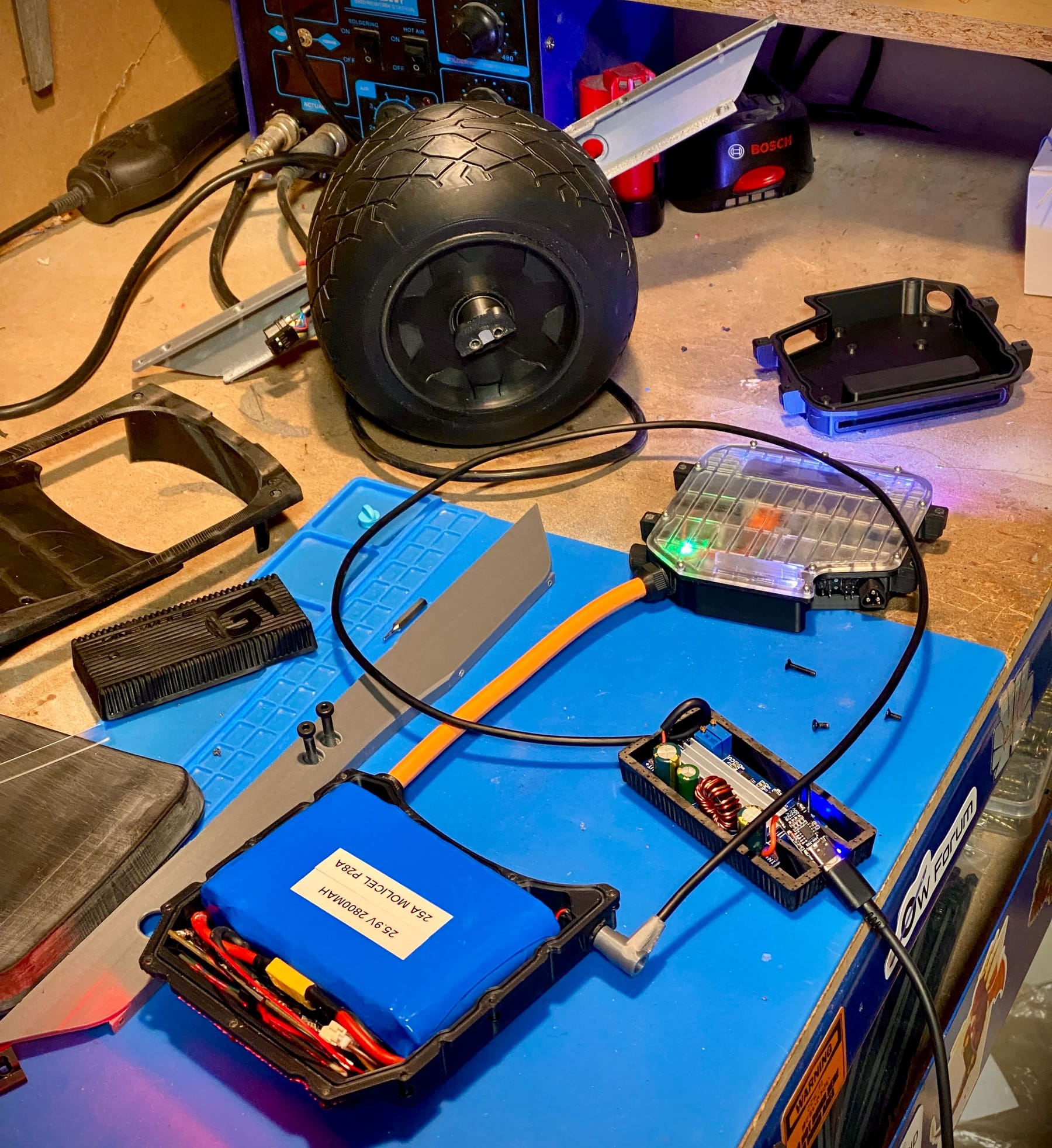
If anyone's got any better idea's I'm all ears :3Before trying with a battery I checked if the board could power on and validate the power being received. Sure enough it was happy ^-^
With all my fingers and toes crossed I plugged in the battery and connected it all up. Surprisingly without any drama it worked and I was able to bring the battery back up to something sensible.
So now came the fun bit. Does it go beep beep zoom zoom?
And now with the footpads set to ghost?
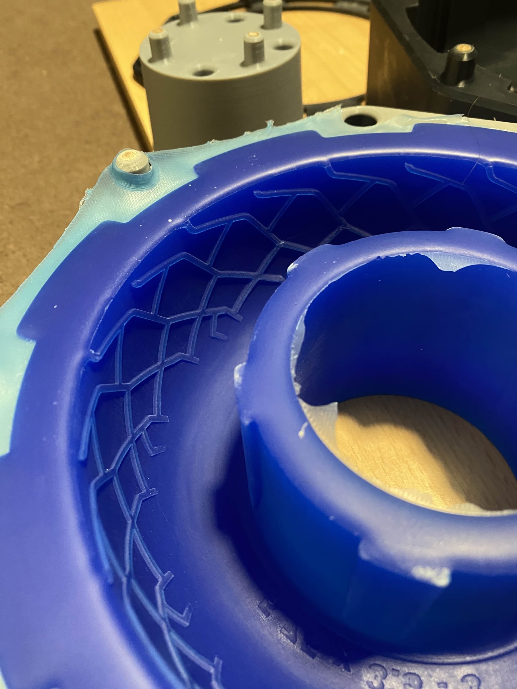
Lil demon child. It's after my ankles for sure! However it's got no grip at all with that PLA tire so it's about time I got that sorted. With a 0.2mm nozzle and 0.06mm layer height I have begun printing the halves of the master tire to make a silicone mould with. It's gonna take a while though at this resolution... like... nearly 40 hours per side and that's not including the outer shell for the moulds which will at least be printed in a much lower resolution.
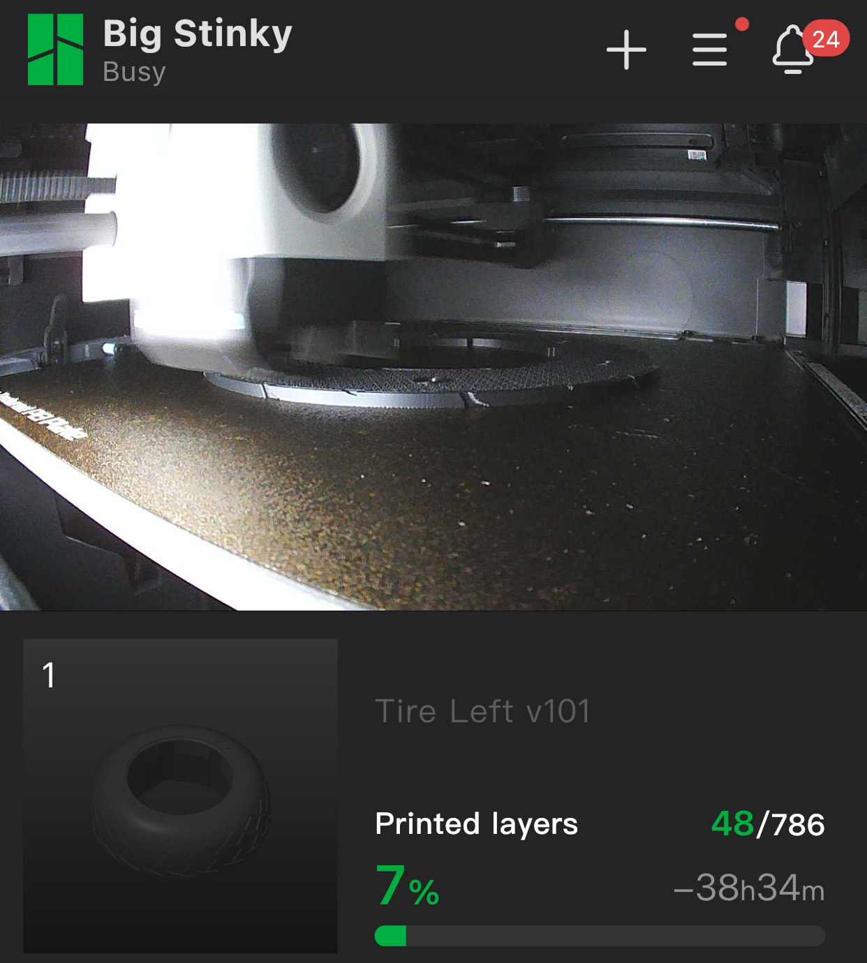
One side is done but still waiting on t'other. Enjoy a glam shot of it before post processing 😊
-
@lia awesome as usual...
-
@Lia I just caught FM's short on your visit, way to go!!! It looks like you had a great time, and I love how much they loved your work.
-
@lia It still blows me away with all the detail and everything is accurate to scale, if i never knew in advance it's half scale , I would swear it's full scale.
Truly beautiful work! -
Thanks guys! They really loved this one. Alec from FM came to find us at Opensauce 2025 and we arranged another visit to HQ. Also swung by TFL the day after ^-^
Kinda forgot to share the progress here. Does anyone want me to do a condensed update from the last update to now or nah?
-
@lia I would love a short one, and maybe a few still pictures of the final product. The rails look so good, how did you do it? Is it paint, decal, wrap, ...? Did FM say anything about it being powered by VESC, or was everyone happy just to sweep that under the rug and enjoy your engineering skills?
-
I'll try keep this short 😅
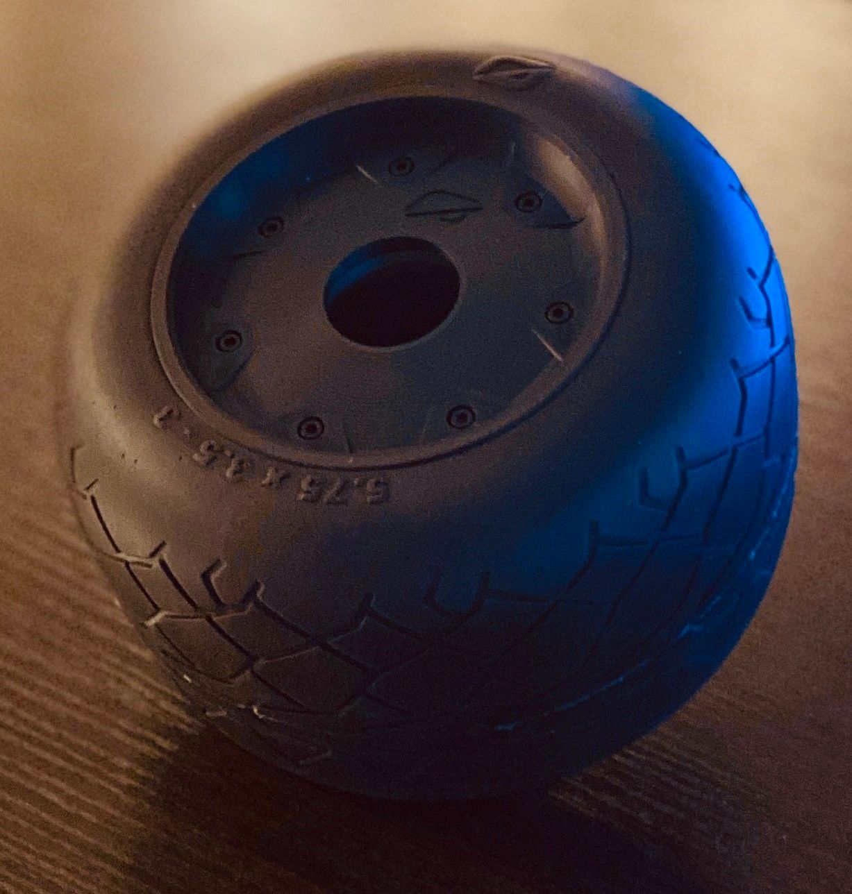
Tire was moulded using a 2 part silicone mould with 3d printed inner and outer casings to assist in registration and demoulding. The silicone was made like last time by printing a master with a 0.2mm nozzle at 0.06mm layer height. This was filled and sanded to get an even smoother finish.
That resulted in this majestic bit of rubber
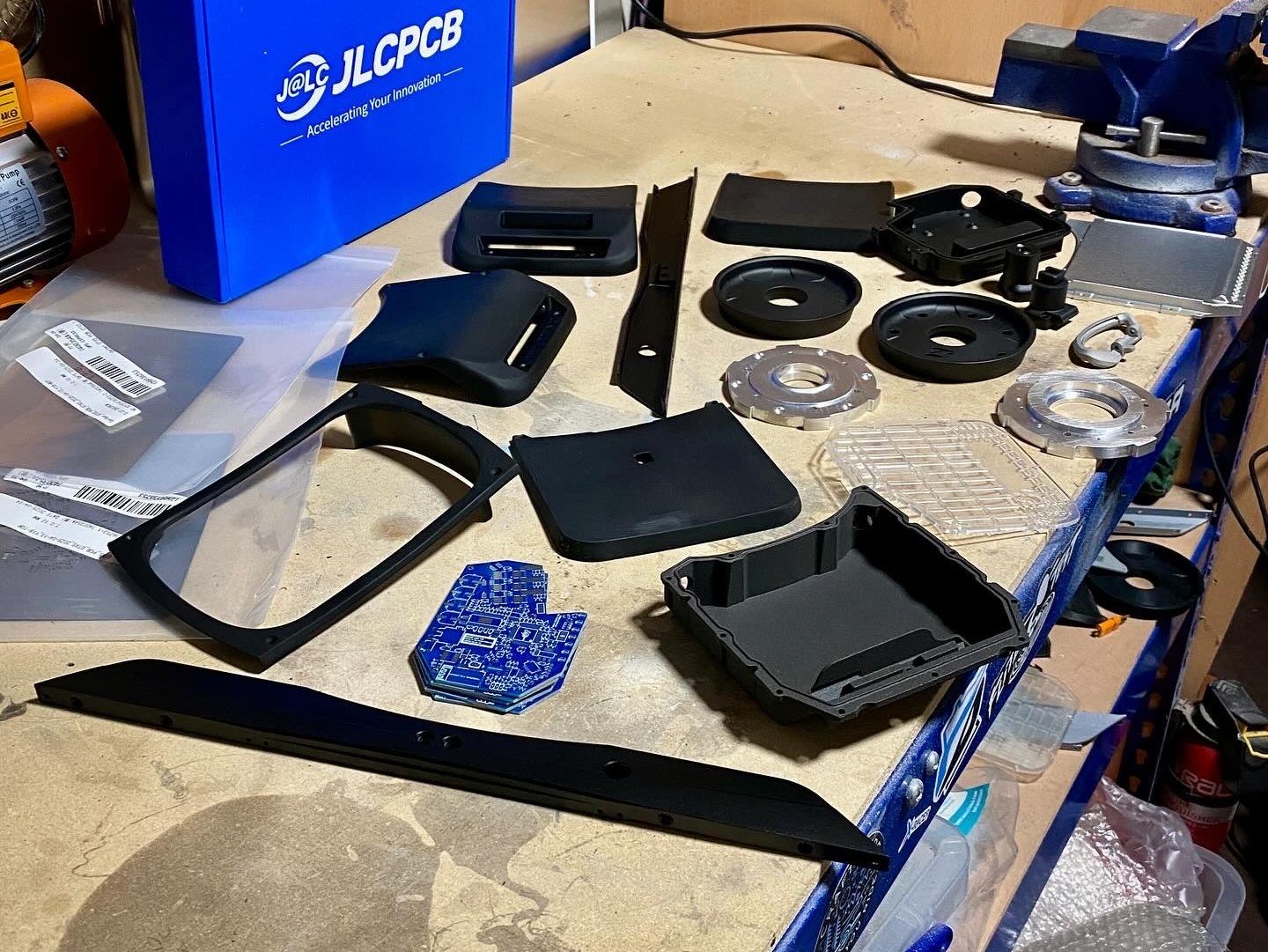
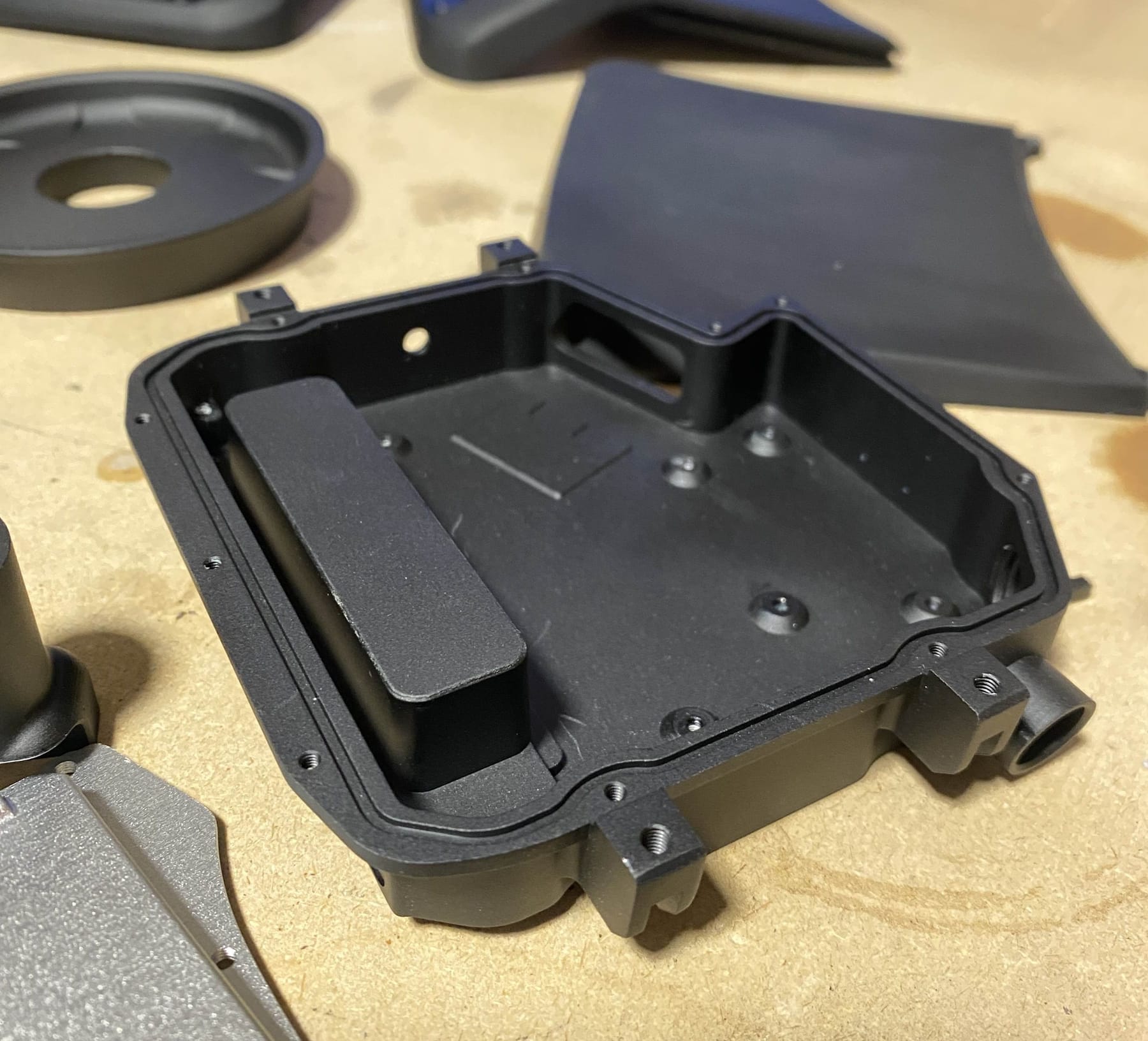
Shortly after I took delivery of the CNC, 3DP and new PCBs from JLC and they looked amazing! Cost about £1k after shipping and taxes buuuuut... like look at how good these came out.
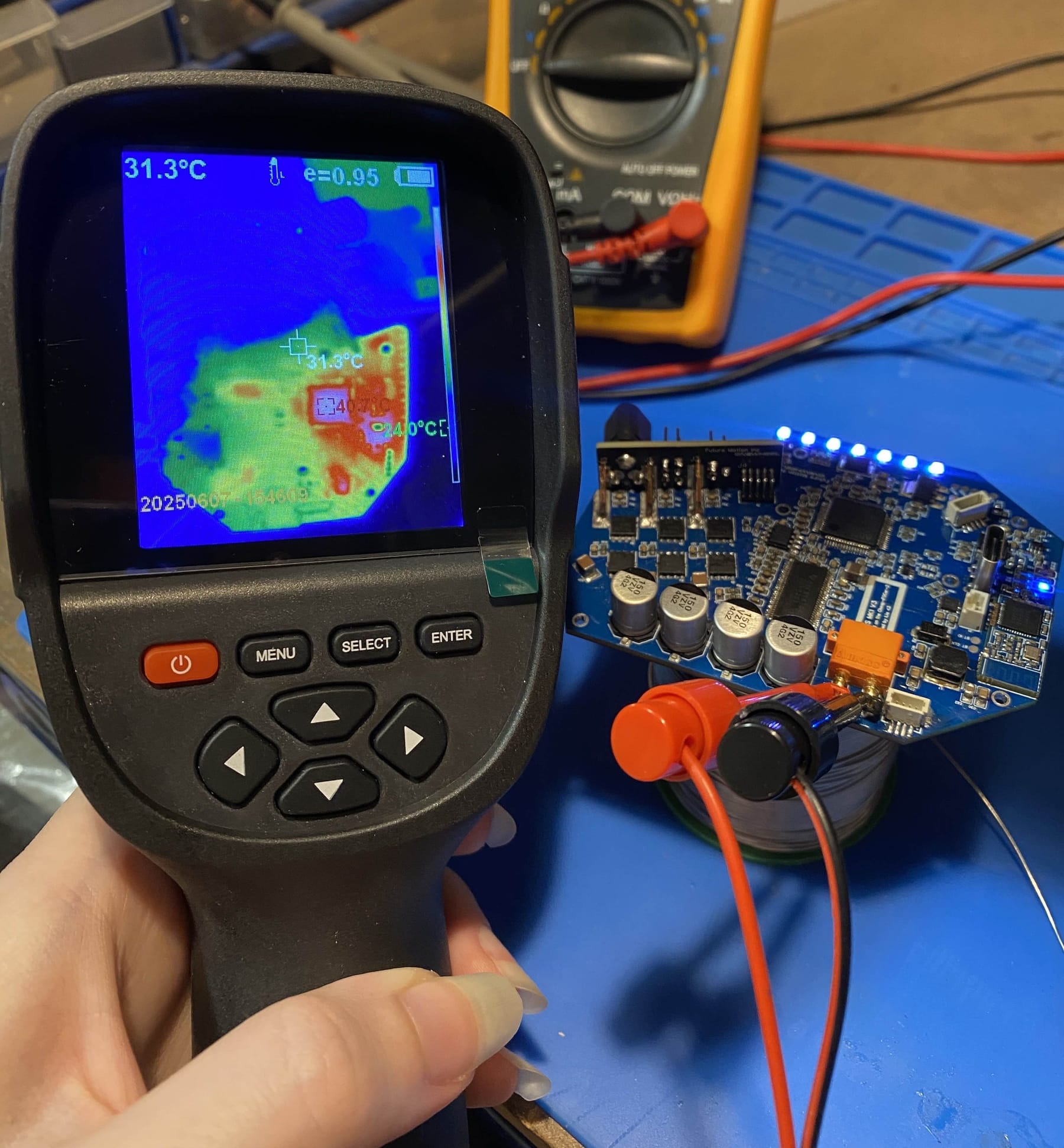
Around this time I also got a thermal camera that I started sanity checking my work. Surprisingly the hottest parts were the 5v buck converter and STM32 package. The FETs even under load and DRV chip were chilling. Likely due to the thermal considerations I took but still they barely got warm. Being Pint FETs I guess it makes sense.
-
Some work needed doing for the charger so I got some parts made up and painted.
Tuning the GTXS was a bit of a challenge. I know a bit more about it since rawdogging the XS with just vanilla VESC so with Refloat installed I was able to get it to a near Apex-like tune. And as an added bonus... this
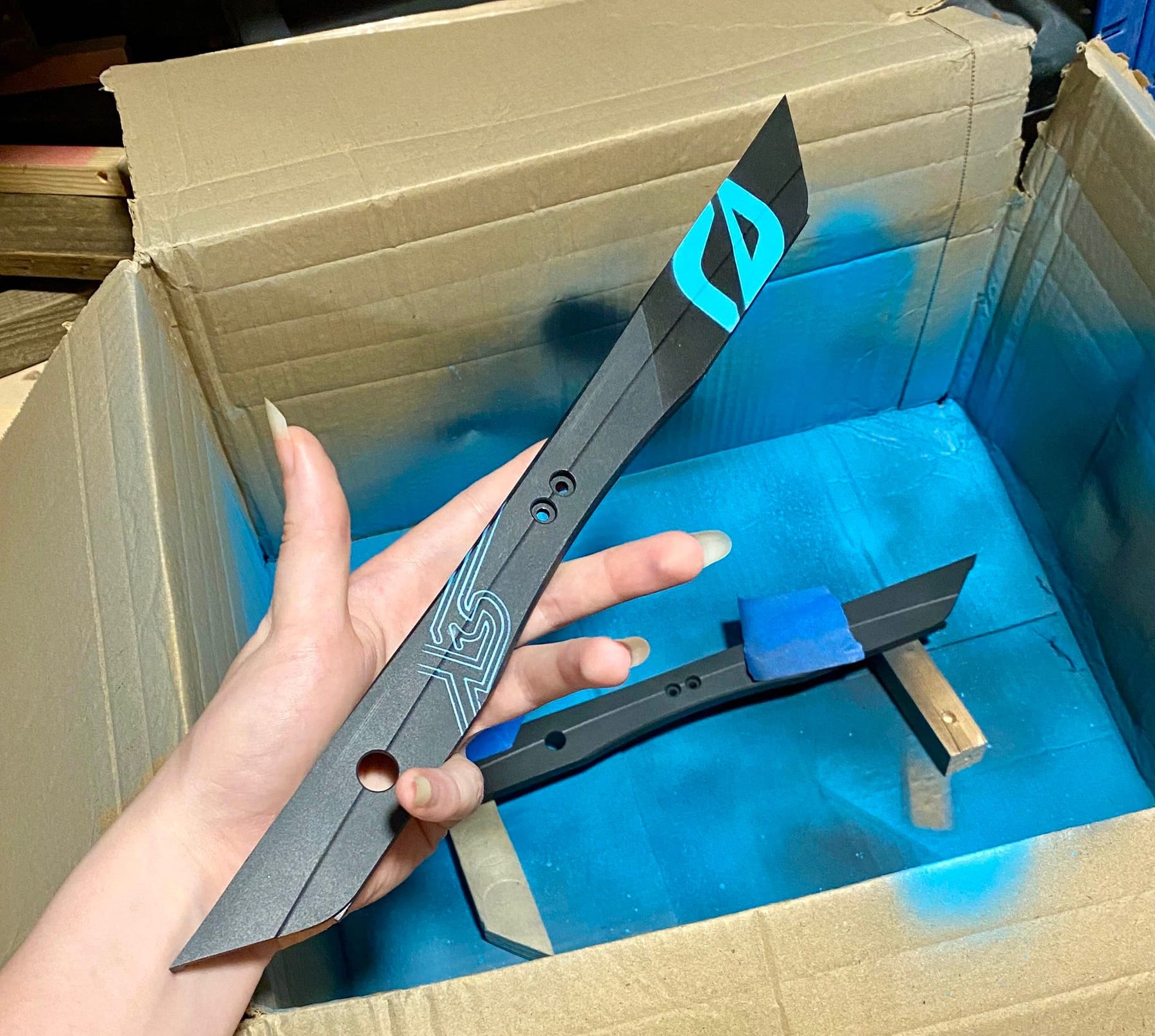
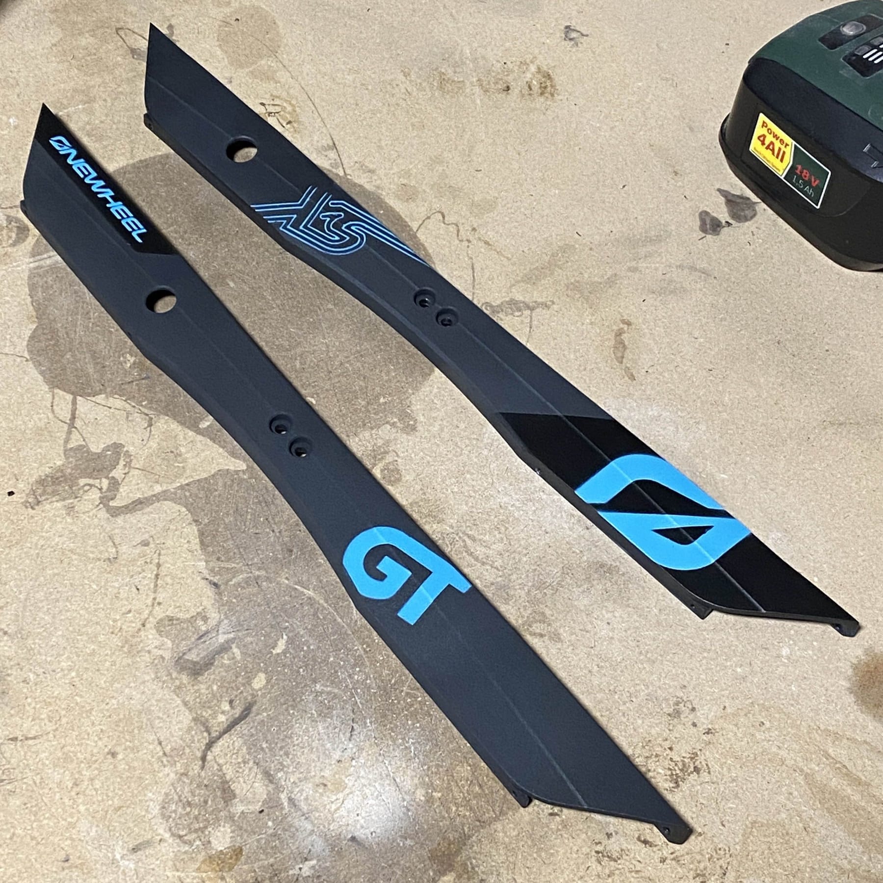
To get the right look for the rails I did some testing with the plastic ones and found I could get away with some resin printed stencils BUT the XS Series decal was way too fine to get spray paint down reliably so one of Nick's friends managed to make a sticker the right size and that worked out for it. The rest are painted on top of a light coating on the anodised rails.
Inside there's a USB PD trigger to request 20v. This then goes to a CC/CV boost converter set to charge a little over a regular 7s setup at 1A. I went a little over to account for the voltage drop from a reverse polarity diode I added that also protects the charge port from exposing Batt+. Even with a cover over the magnetic port I wasn't keen on leaving that exposed.
With the metal parts the build was getting heavy. Without it all together we were already at 3.2kg. Despite this it was able to bonk a little. Sadly the footage I have of this is hella low res for some reason. However it was enough to get a repost on stories from Bohdi on Insta so that's pretty dope.
With a few final touches and accessories to bring with we had it all good enough to bring to Opensauce.