Trace Map Continued
-
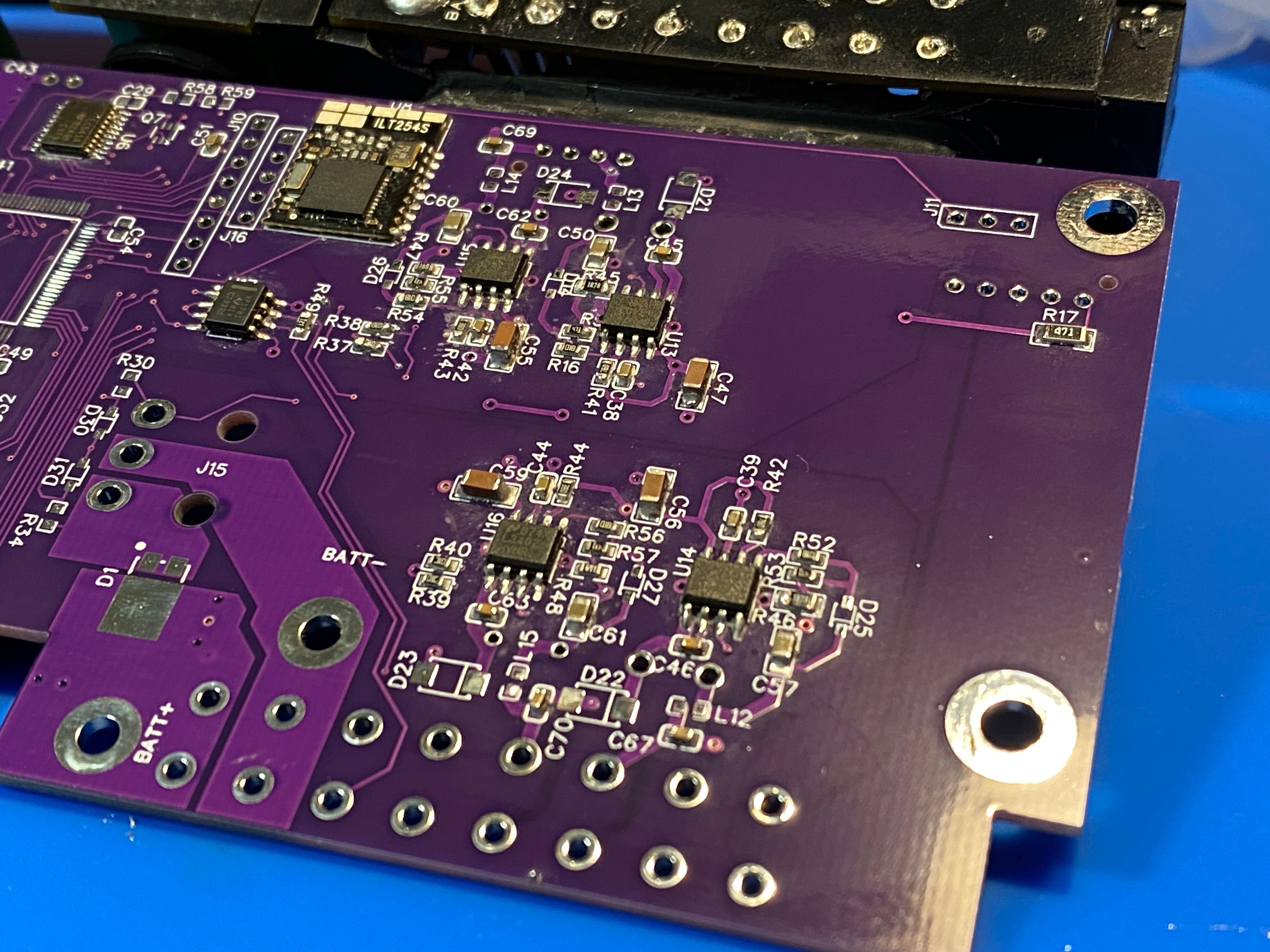
I'm gonna be a busy girl this weekend (The LEDs came too)
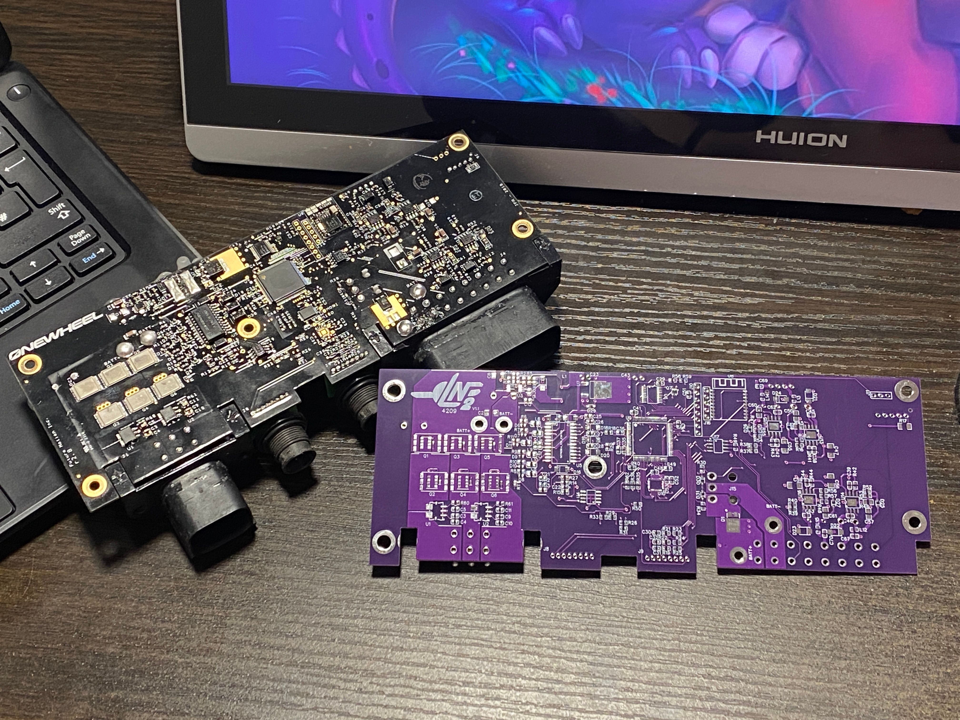
Did this in purple because white is like 2x for some reason. Didn't want to do black since I might mix them up lol.
It's going to take a while doing the transplant since I'll be measuring each of the passives between desoldering and re-attaching so I can fill in the schematic and get the next revision done as PCBA.
-
Progress is slow. I realise I missed C68 which appears to be some sort of filter cap on the front LED side. Oh well. I've measured all the components I swapped and with Nick's help of writing them down as I read them (sped things up a lot) I've got most of the LED side and the current sensing part of the ESC side done ^-^
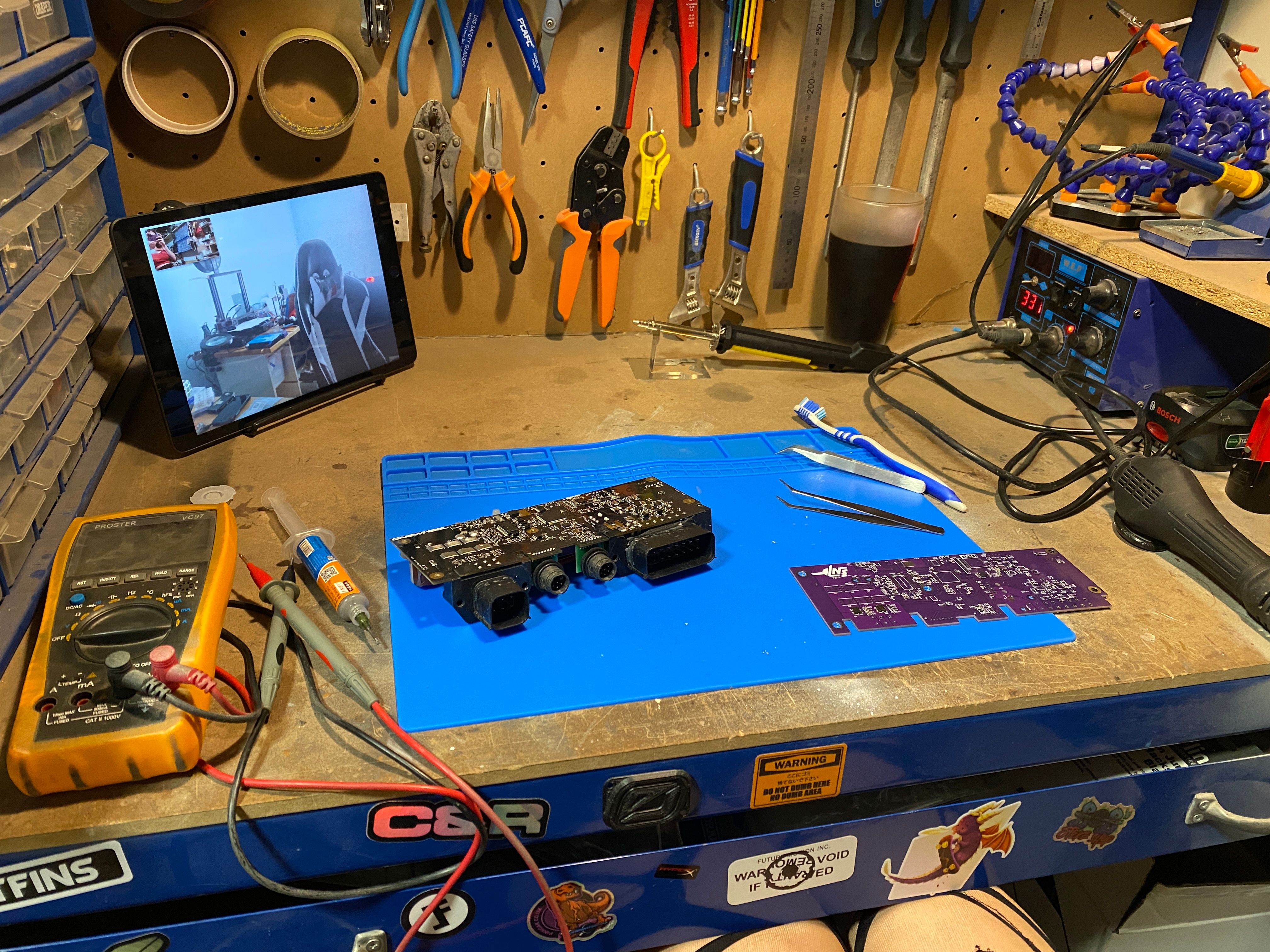
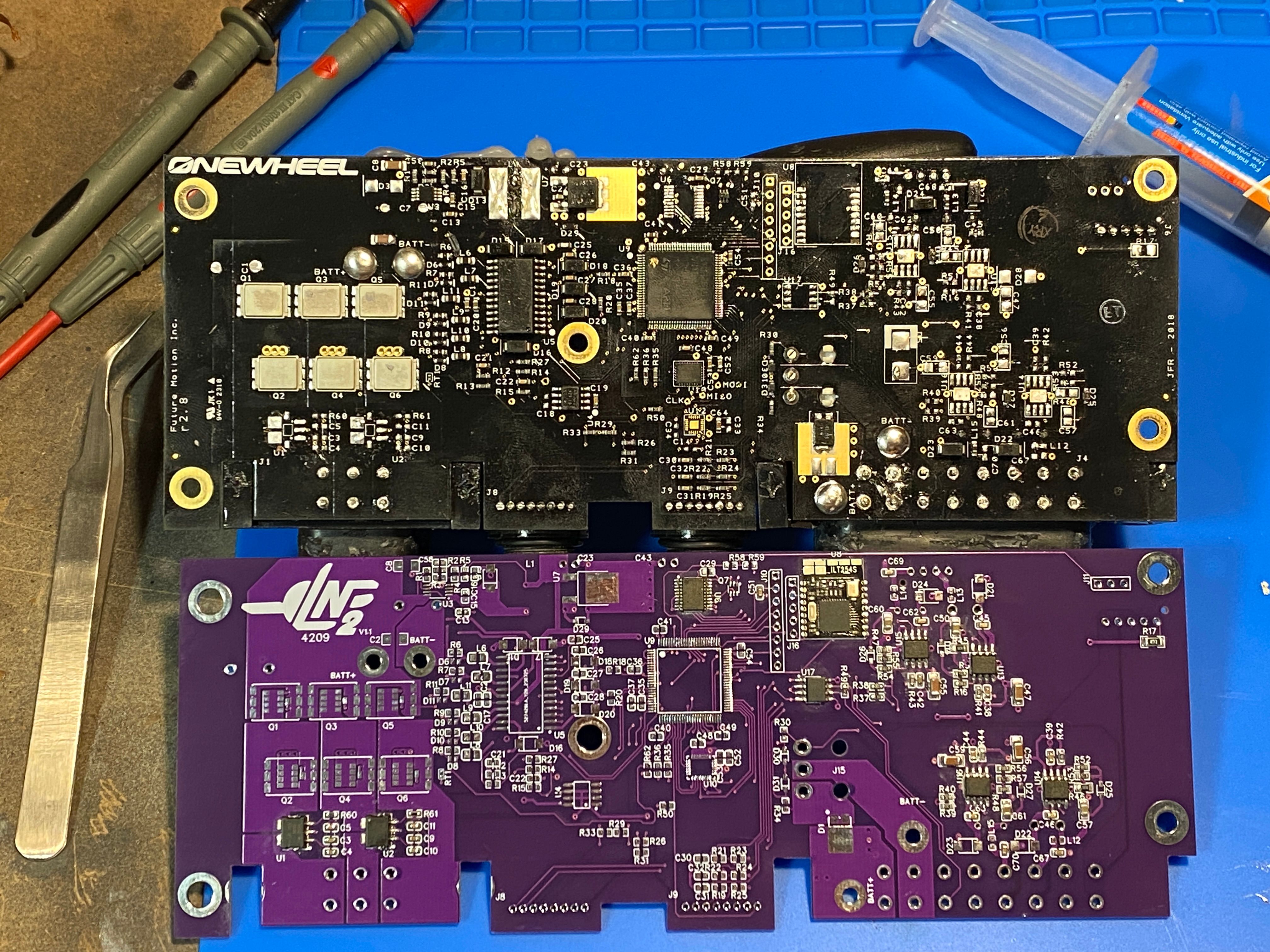
-
@lia great work indeed.
Is that the 4 holes by c68 for the LED riser ?Just thinking in advance for trouble shooting my dodgy LEDs ;)
-
@puzz360 It’ll all stock on v1.1 however v1.2 will put the led segments on modules on the reverse. The idea being I want to replace the leds for addressable so a modular approach means choice and an ability to only do a single side ^-^
I’m taking measurements so if you want to pass values of suspected bad parts by me let me know :)
-
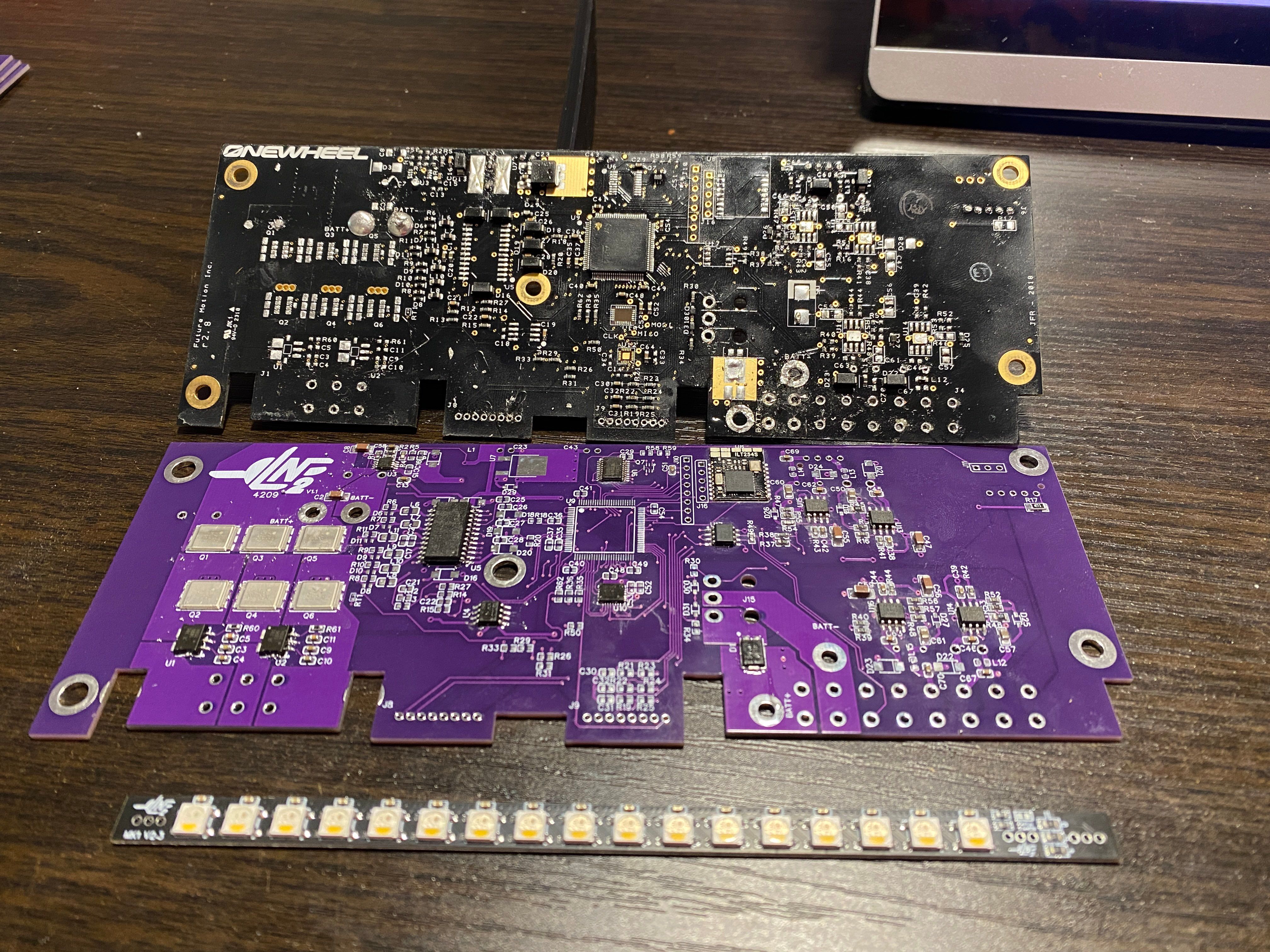
Painfully slow but more is off, a lot of the chunky connectors and components on the large voltage planes.
-
Was sweating bullets with this step...
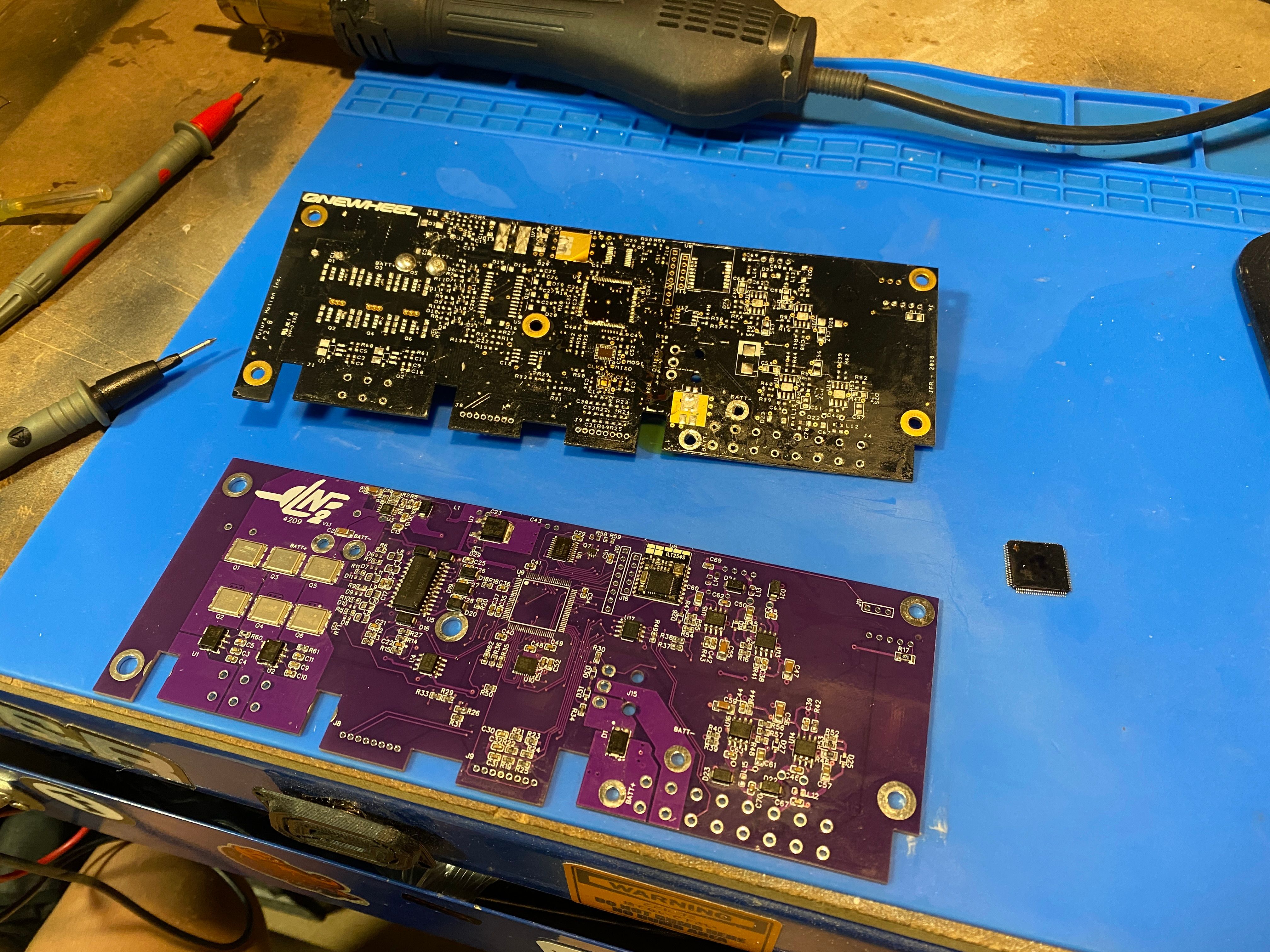
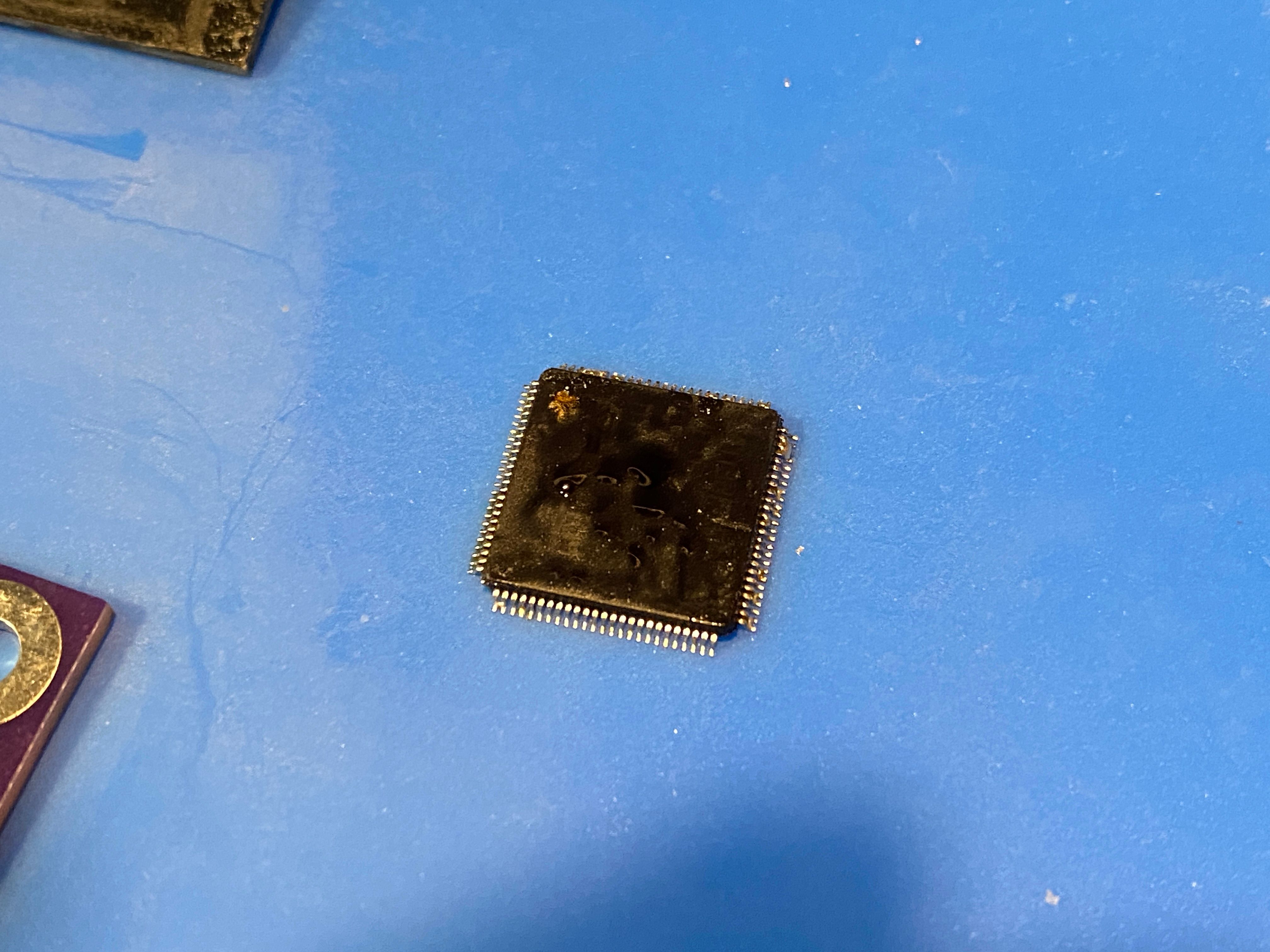
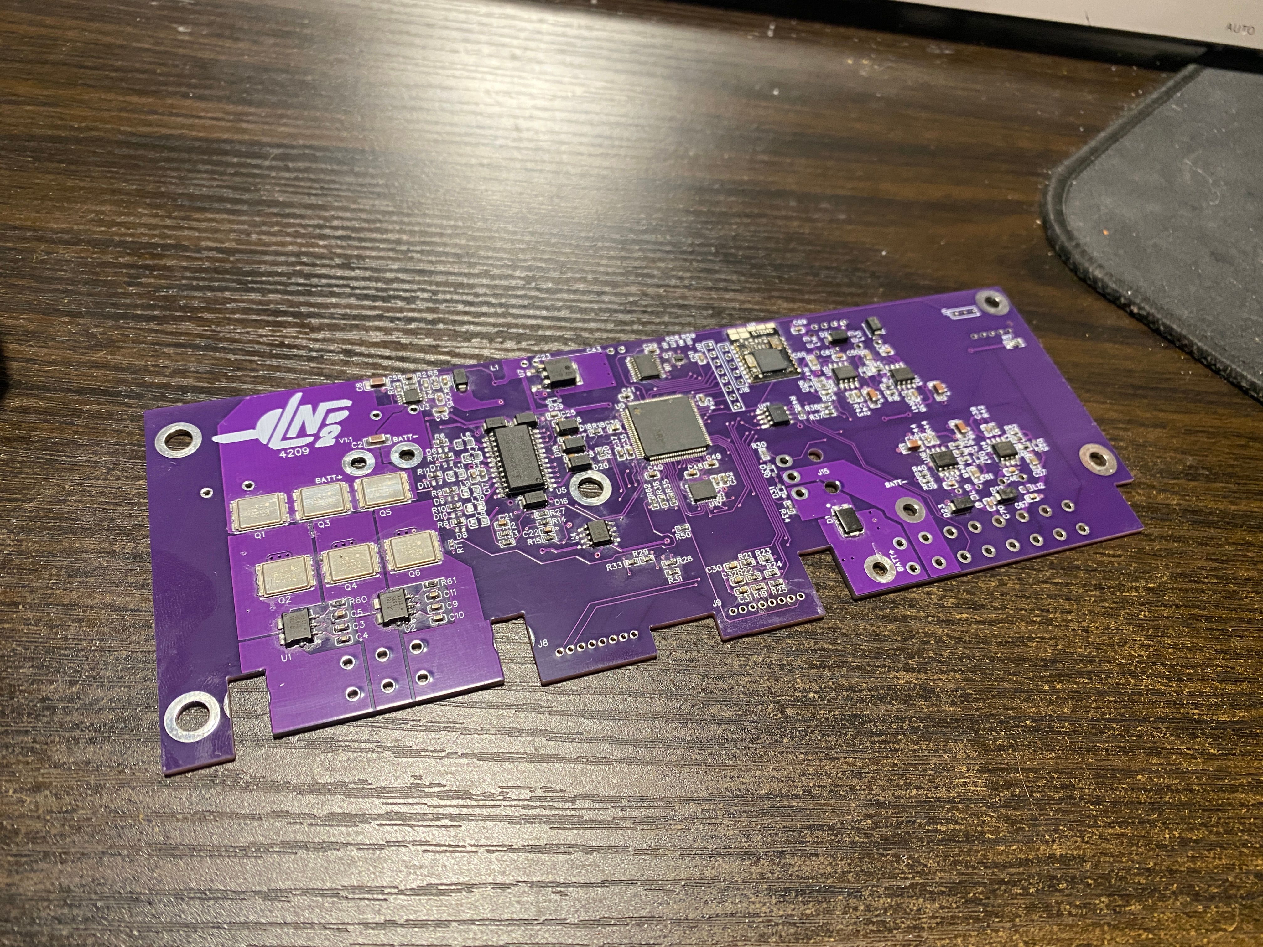
So far it looks happy from some "kinda sorta not really" scientific measurements to validate no massive mistakes. Got a few diodes and smt inductors to migrate but since I have no way to identify those parts I haven't moved them yet. Everything else got measured so you best believe I have an almost complete schematic for an XR controller.
-
I have been so busy it's unreal.
Got headhunted and am doing some CAD professionally (yay) while trying to finish up those LEDs and balance a social life (not doing well at that one).In the meantime look who's been put together.
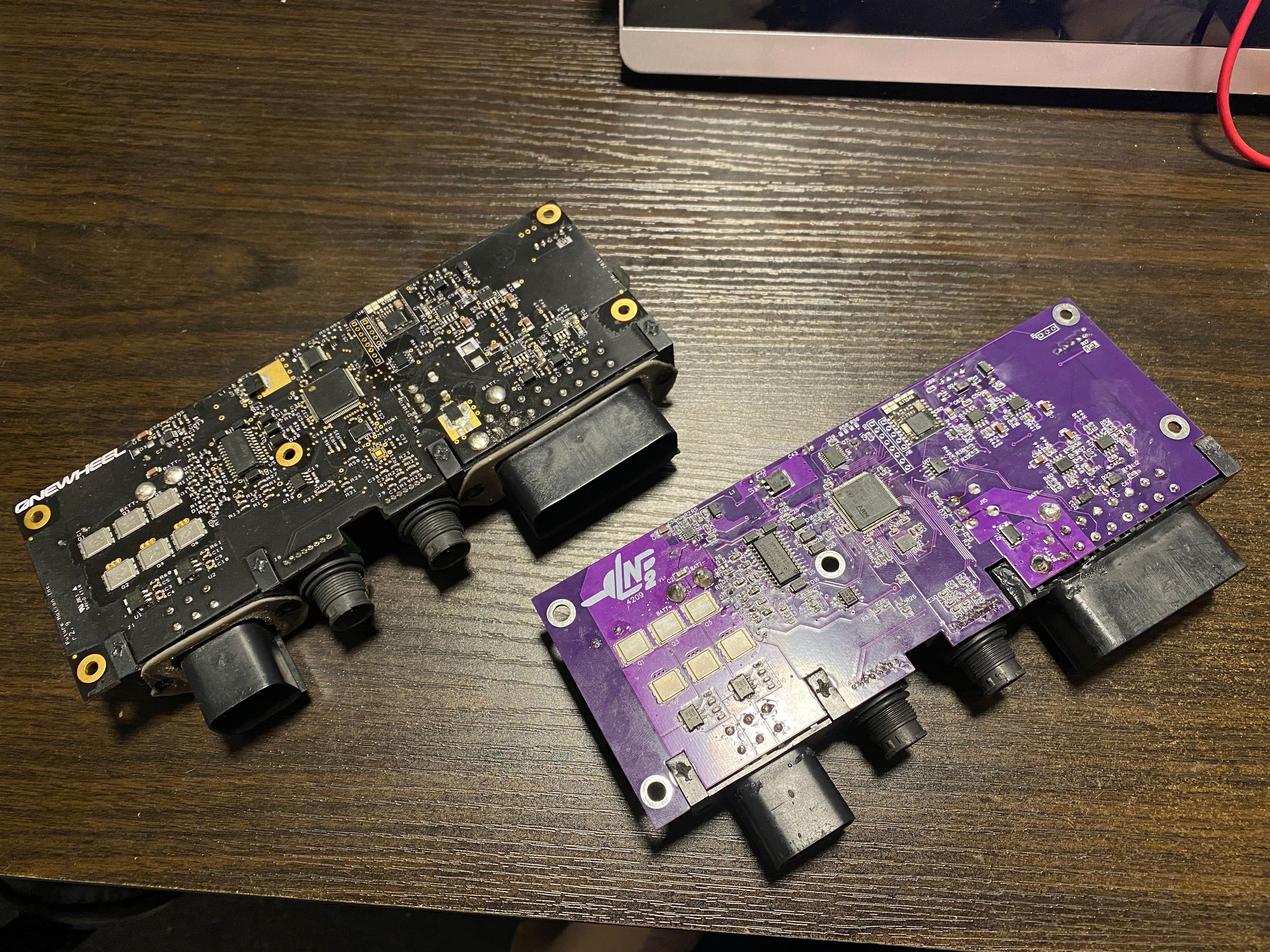
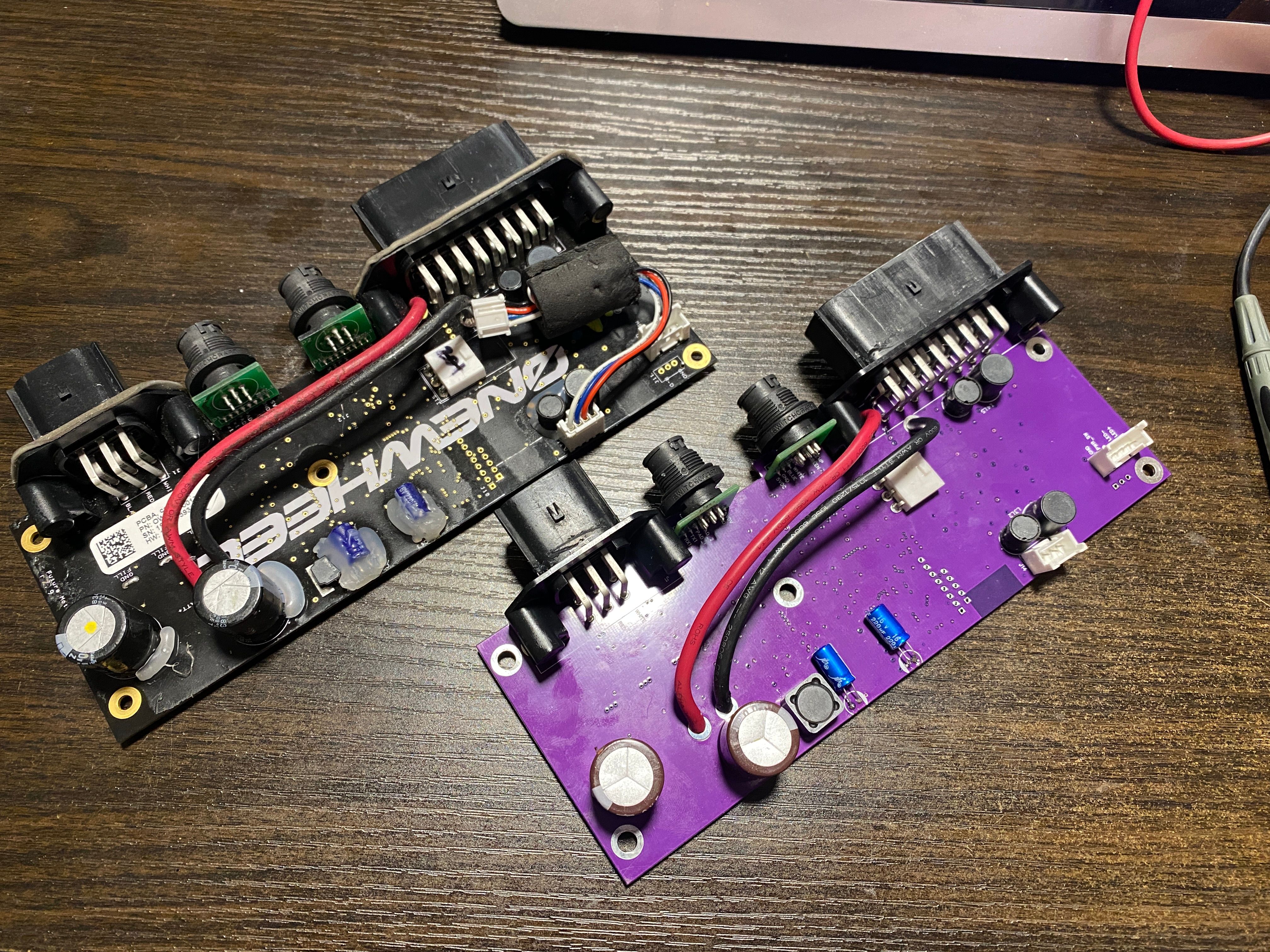
I did power her on...
aaaaaaaaaaaaaaand
... She didn't boot :((( No blinky flashy light.BUT she didn't catch fire so it's a win in my book. Good thing too since I was using the old "jam the charger in Batt+/Batt-" trick rather than build a battery and didn't want to blow my only XR charger. I'll slip my 30V bench psu in it next time so I can measure the current and figure out more while probing for expected voltages. It looks like the primary buck converter (U3) isn't doing it's job, that or L1 is being stinky.
Either way I need to spend some time diagnosing it properly and not just hiding at the edge of the desk with a pair of safety squints. I am after all a professional ^-^ Got myself a proper docs coat too so I can look all serious while I perform
surgeryrepair that some consider to be unnatural. -
@lia Congrats on the professional CAD work :D this is so cool to see work on, hope troubleshooting goes well :33
-
@glowkitty Thank you <3
Me too, going to probably be a lot of "lol oops" as I do -
It lives :3
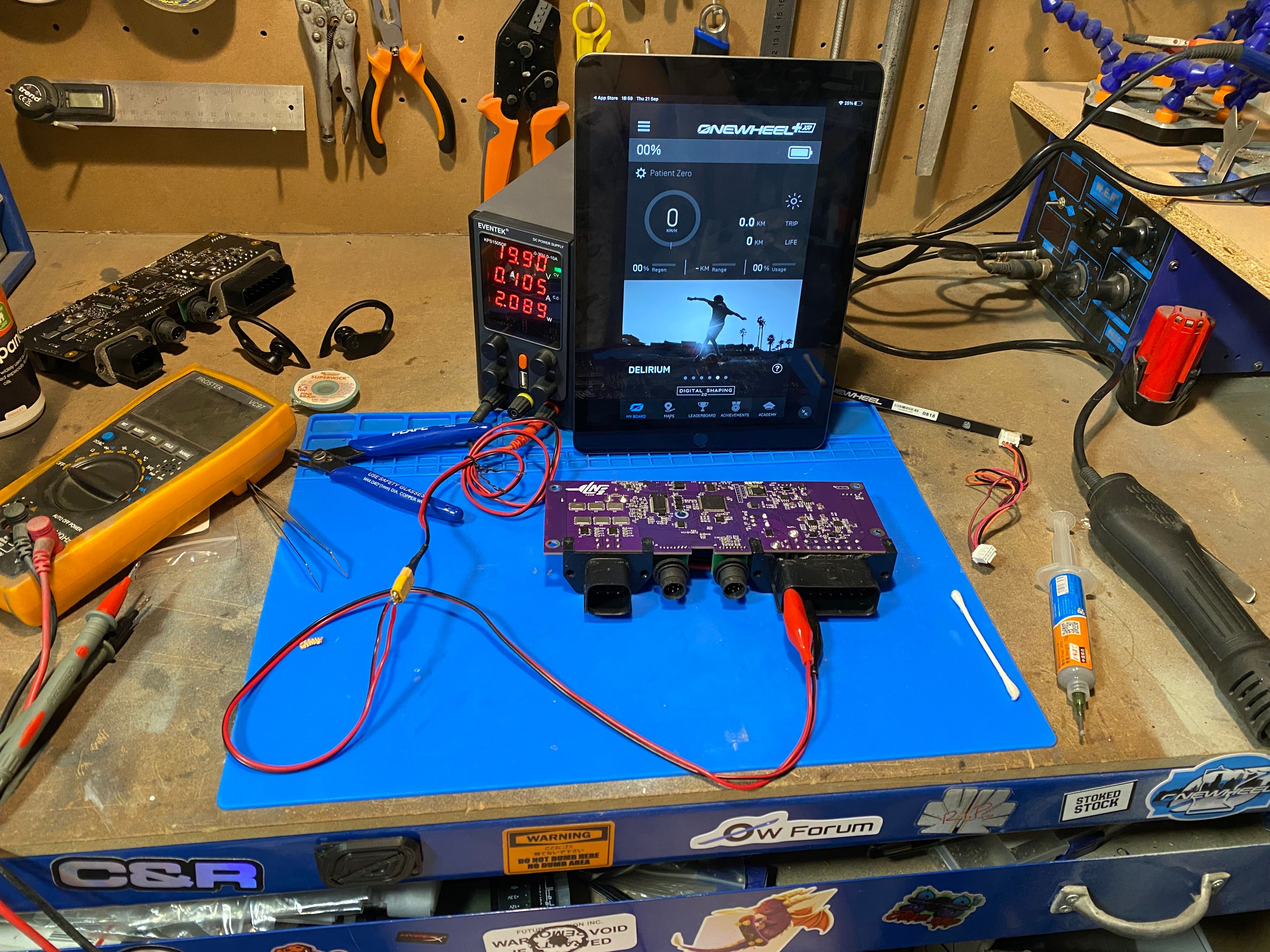
Undervolting it for testing so I run less risk of killing anything if it goes wrong and also I didn’t want to blow up my XR charger lol. It’s not completing the boot process to give me an error code but I assume if I give it the expected range it may successfully complete the boot process.
Edit 1
Worked up the courage to use my charger to power it and it’s still powering on but other than getting the basic stats off the internal memory it’s failing to finish the diagnostic check. As such no error code still to confirm it’s awake.
Never seen this before but the board status is literally 0 with no gyro reading which further makes me think it’s stuck trying to complete the diagnostic check. I think the lack of gyro suggests that chip isn’t working correctly and holding it up.
According to FMs own patent the diagnostics occur before any error code is given which makes sense. Thus it must be getting hung up on one of them.
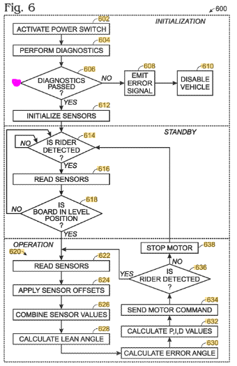
I’ll remove the gyro hip and see if it changes. Failing that I’ll need to start taking other things off like the mosfet driver. Anything that directly interfaces with the STM chip which could be holding up thee diagnostics check.
-
Planning on picking this up again as I want to make a better XR but while doing a bit of casual research for another project I found I'm not the only one that managed to clone this PCB.
Take a look at the one on the left and then compare it to the pic of an XR controller on the right.
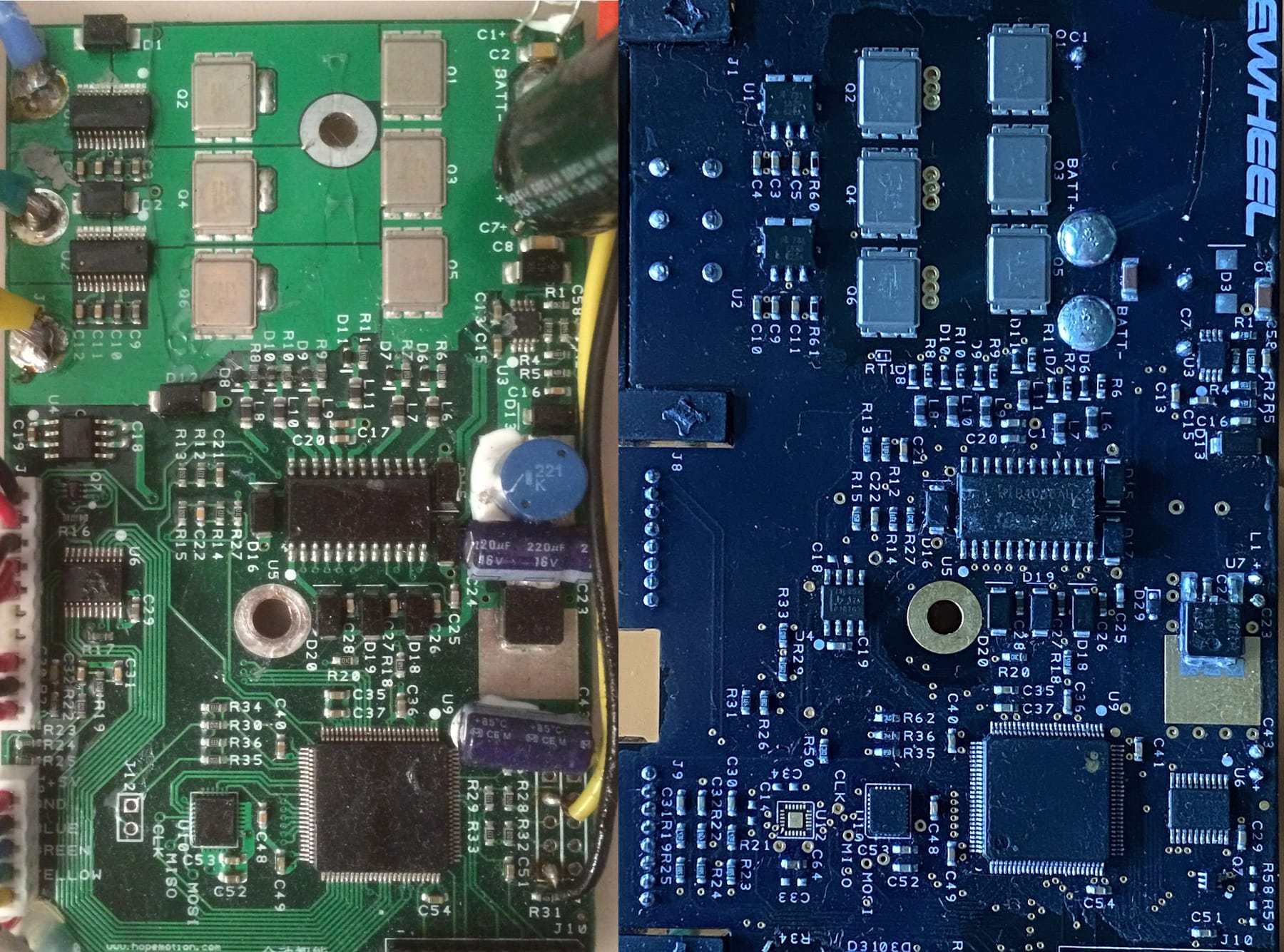
Bear in mind the current sensing chips beside the motor connector are actually also the same as on the V1/Plus. Everything is the same, down to some of the silk screening.So what is it? It appears to be a controller for an EUC back from 2016. I found the image on a forum (linky). Image courtesy of esaj.
I did a bit of digging and traced the company called HopeMotion whose website no longer exists but archive.org got a few links saved. https://web.archive.org/web/20160308233001/http://hopemotion.com/

The company states in 2013 it "is mainly engaged in the development and industrialization of high-efficiency and energy-saving motors, drivers, and controllers for electric vehicles. The company has a group of high-quality R&D and management teams".
I assume FM either worked with them or had them manufacture their initial runs in which the PCB design got yoinked. The only information regarding the cloned PCB starts in 2016 which is well after the kickstarter for the Onewheel completed and a year before the Plus.Anyone know more about this? Maybe worth it's own topic if there's more to this.
I did initially assume this may have been related to the CES incident back in early 2016 but I couldn't find a connection.
Anyway in other news I've managed to get my hands on a 4212 PCB (for a repair I'll post about another day) so I can work on redoing the design on a more modern layout minus the stuff that bricks modding.
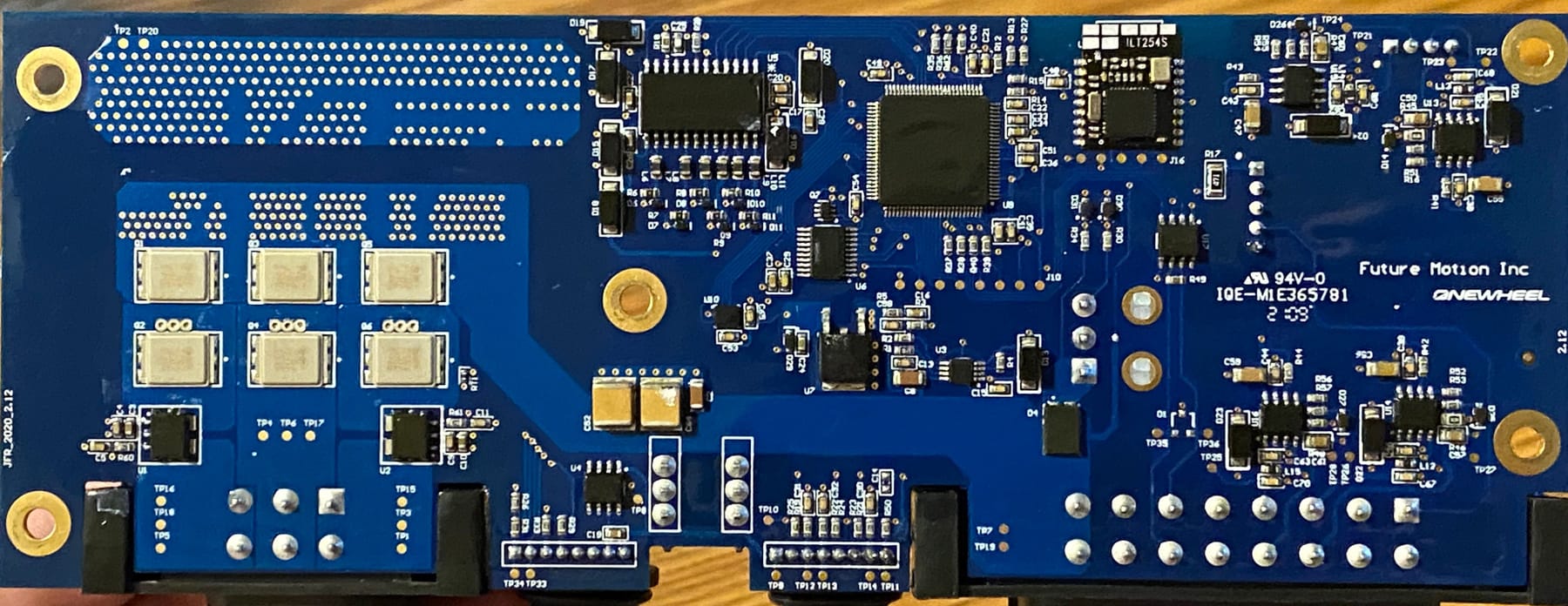
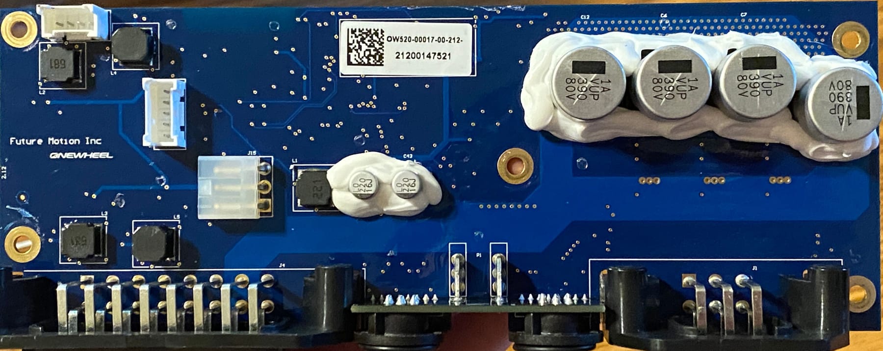
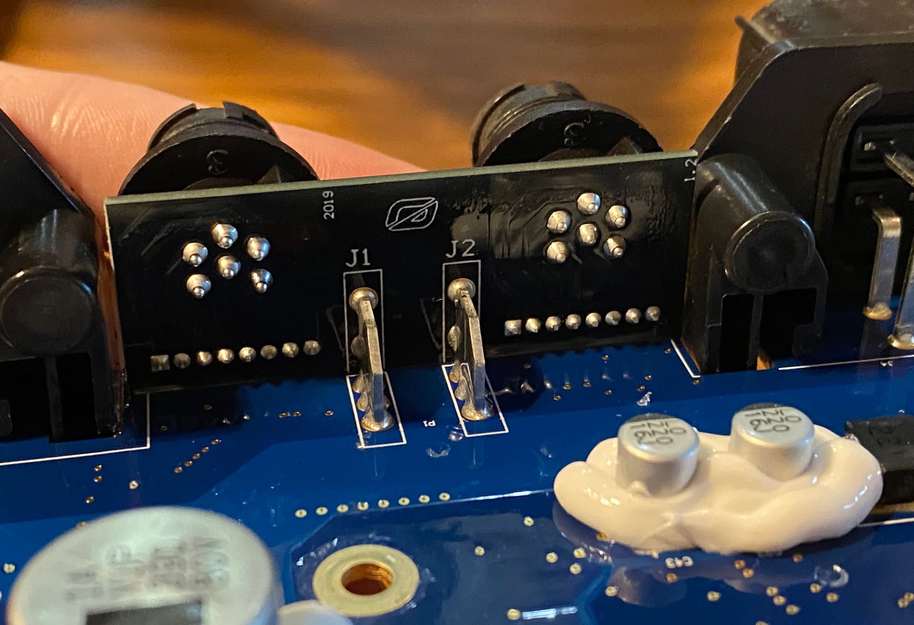
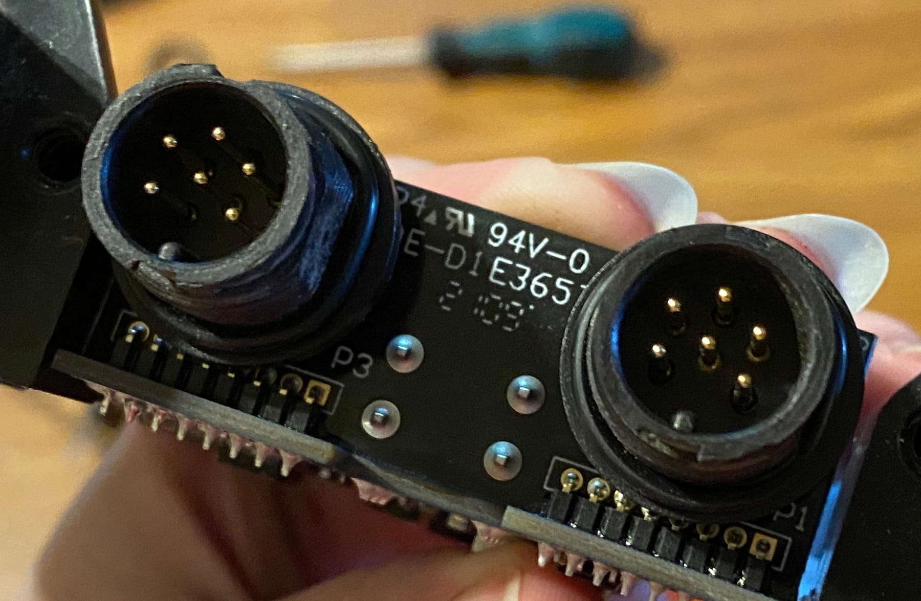
This redesign was more sensibly designed with no need for the large power wires jumping the PCB. Also the motor and footpad sensor connectors got a well needed reinforcement.
-
@lia I saw you missed C68 on your pcb, I’m dealing with a 4212 board that C68 appears to be bad. Do you happen to know what capacitor it is so I could order one to try and replace it? I’m pretty new to this and can’t seem to find anybody other than you who has posted so much and has the knowledge like you seem to have so figured it was worth the ask.
-
@tribacon No problem. Just pulled up my schematic and I have C68 down as a 2nF 0603 capacitor :)
Good luck with the repair!
-
@lia Awesome thanks! Now to hopefully find some local so I don’t have to order 4000 from Newark!
Started with the Error 21 issue!
-
I finally fixed it! Turns out past Lia sucked at reflowing. A few chips had pins that looked connected but weren’t and the IMU wasn’t fully hooked up.
But now I finally have it booting up 🥰
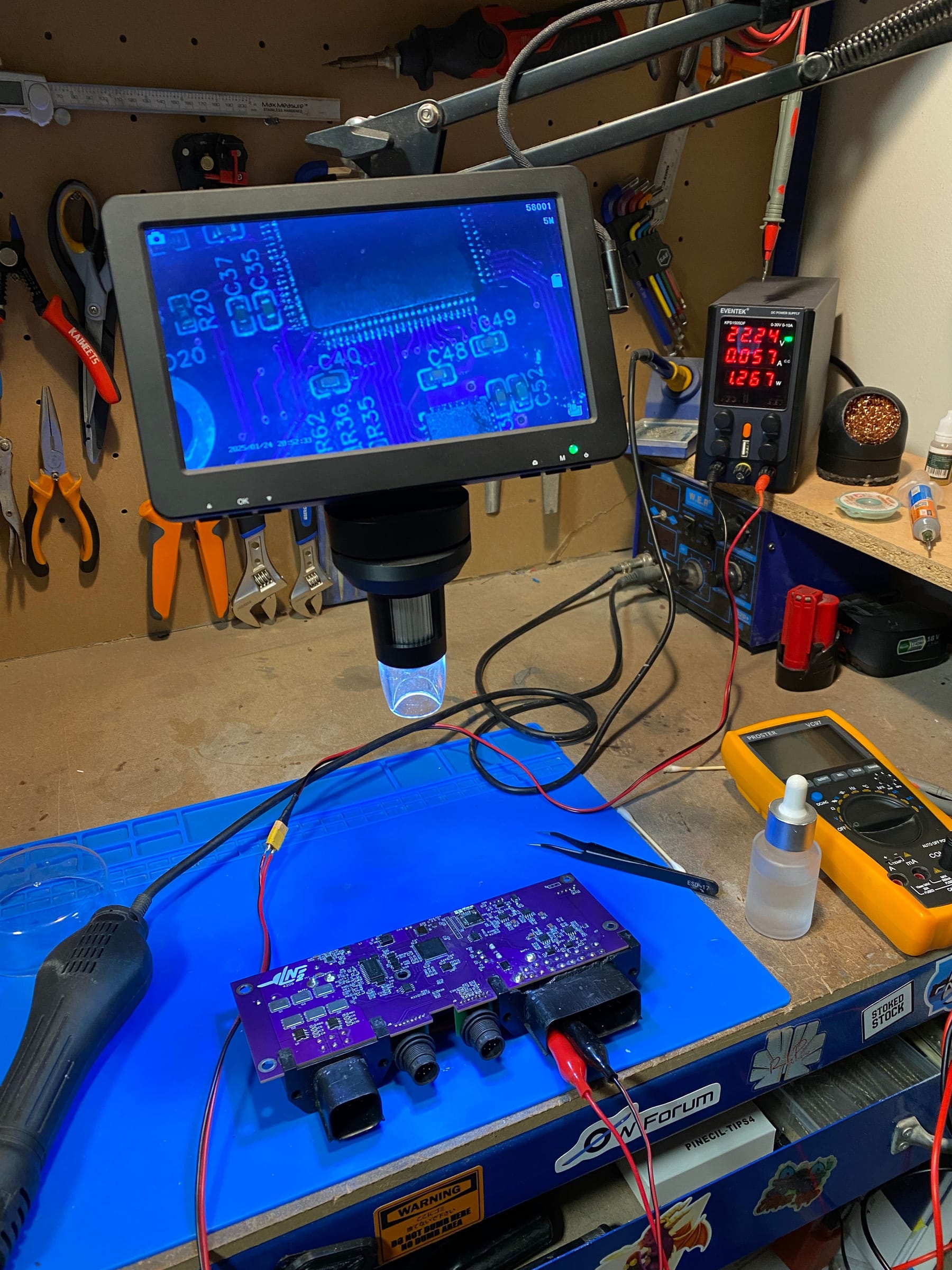
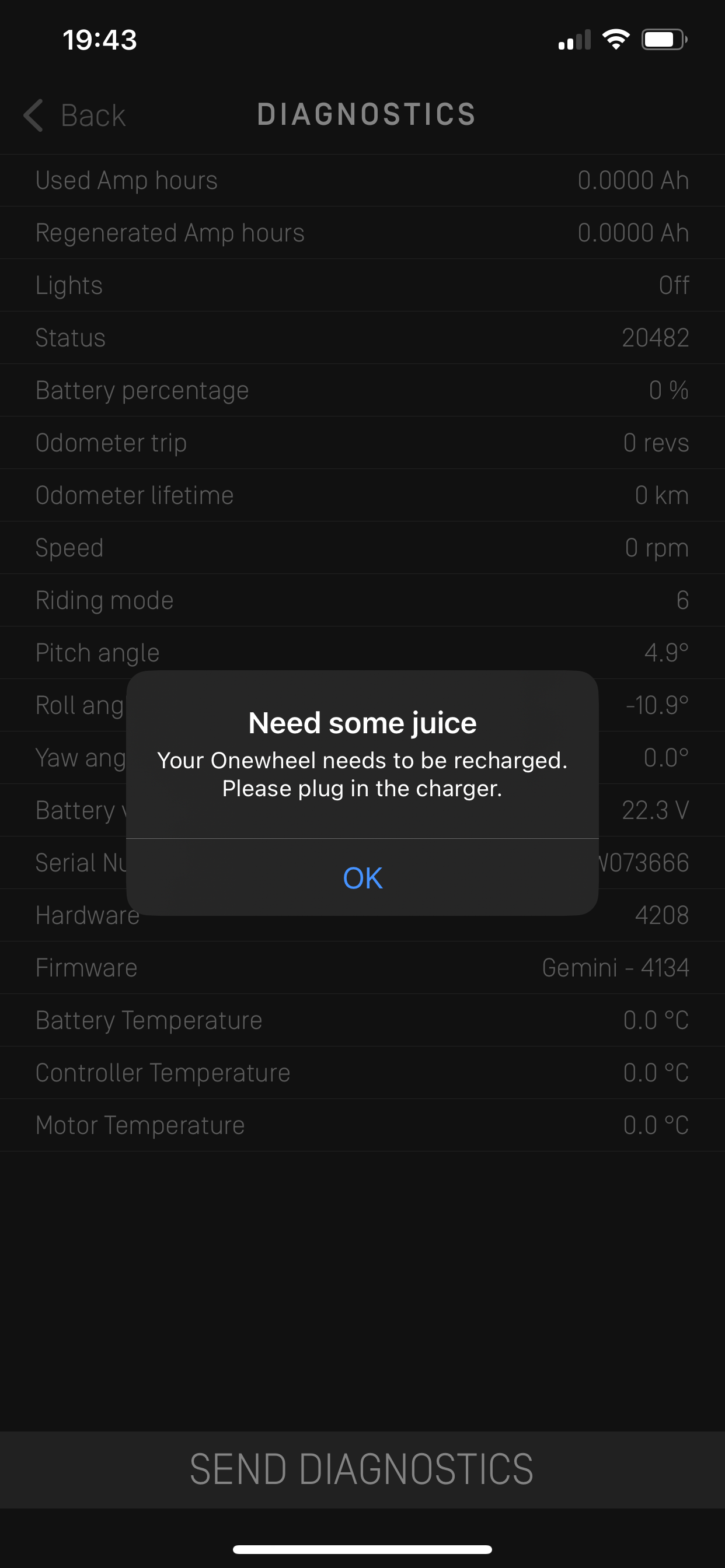
I guess now I should probably consider putting it in a board and taking it for a spin then maybe make some upgrades!
-
@lia This is some insanely awesome work! I haven't used forums in forever and just registered to applaud your work! I wish I had known about this and I could have helped you with component values, trace maps, x-rays, etc. I have heard your name came up multiple times now in this space and every time it's something amazing, Hope to one day be able to meet you!
-
@atlowshop Thank you 🥰 If you're ever in the UK lemme know ^-^
Might be taking a swing at the GT next. Would be fun to try putting an XR chip on a GT controller or other ay around and see what diabolical creature I can build. -
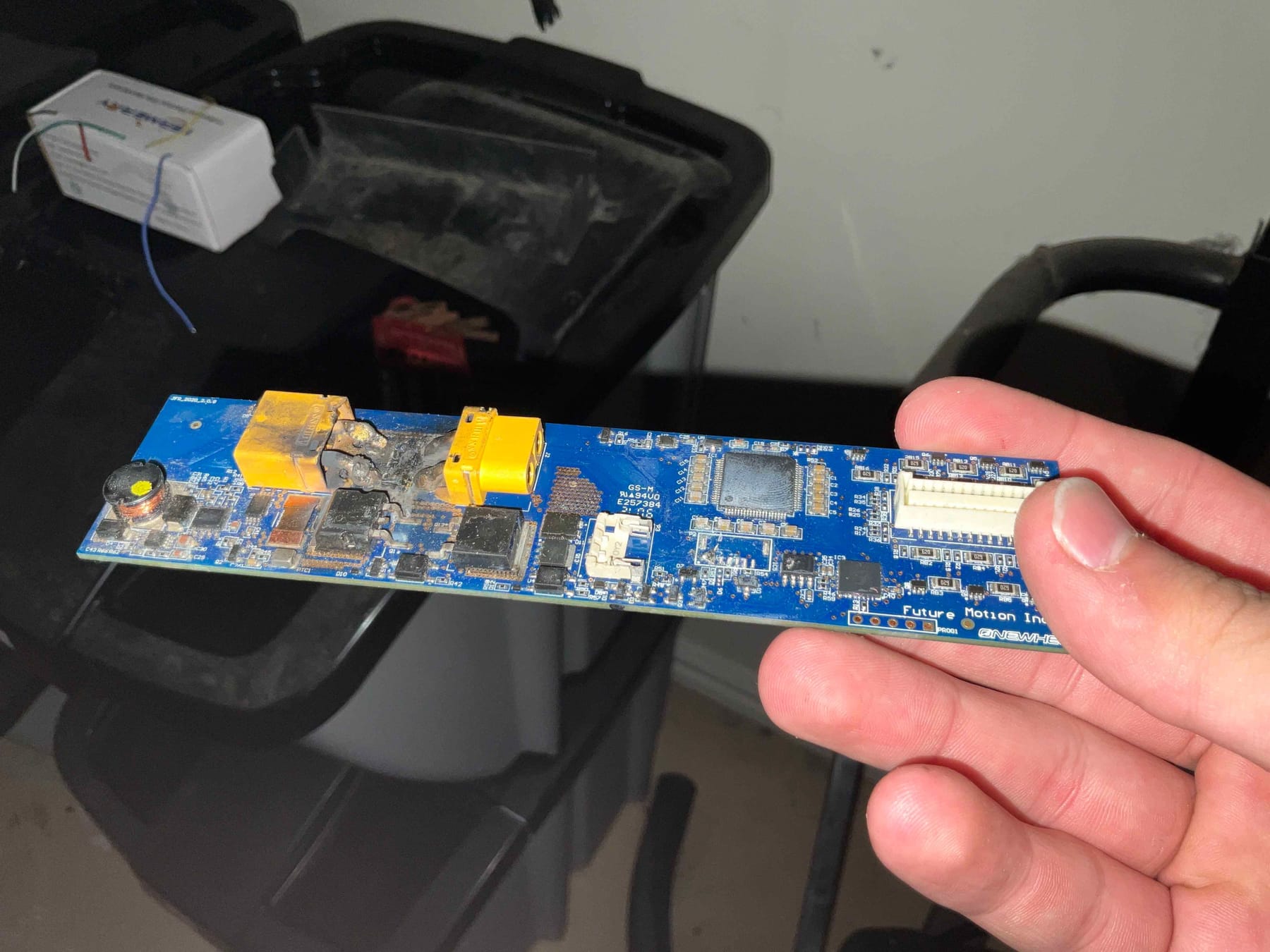
@lia I don't know if you're interested in it, but I have my old XR BMS if you want it
It's a little toasty but it still powers on! -
@loaffette Thanks for the offer. I have a few at the moment so should be fine 🥰 Appreciate the offer though. Toasty in what way though? Got me curious about that bit :3
Haven’t had the desire to take a swing at the bms but it might be worth it since I’ve had to fix 3 of them without schematics.
-
