XR resurrection
-
@sirgu thank you! I hope so… it is my opportunity to finally have my one wheel! Hahaha
-
bms 2110 here is the bms board. For the record xd
-
@vulkito Oh yeah I see the knocked cap on C11. Bet that was the previous owner pulling the XT60 out and accidentally catching it.
-
@lia yeah, i bet that the previous owner didn’t put too much effort on opening this up and i doubt he followed the disconnecting order of these connectors (which could also be the origin of this). In any case: i ordered a new rs-485 and i will look tomorrow for capacitors, but those on the pic… i have no idea of what to use there (i would say those are generic capacitors on the input, but the values is a different matter…)
-
@vulkito The 4212 bms pic 1788 chip is locked and cannot be flashed. The chip has to be replaced , however you can use an earlier XR bms with the newest Owie chip.
You can reflash a Pint bms to Xr.
I bought a couple of 1788 chips in case.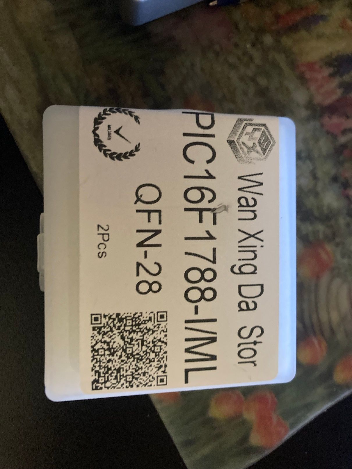
-
@vulkito What happened to the pictures of the bms, I can't see them.
-
@lemur i hve a couple of pics in my cart already hehehe. But now the question would be if i can install a new pic (flashed with an old firmware revision) and would work (+owie). I would say that the hardware at logic level is the same (but i do not have a board to compare). If this is the case i can search for a 4209 firmwware and test. The bms is already out, soooo i guess there is nothing to lose xD
-
@lemur i can see them on the link. Does it guve you any kind of error?
-
@vulkito Oops, didn't click on the link.
-
Ok, some news:
C33, c34 and c35 are ok. Removed from the pcb to try to isolate the short with no luck (at least i measured the cap values).
I desoldered gnd from the 1786 and looks like that this one is not shorted either. I still have a short between gnd and vcc, so either the pic is shorted or i think i should go to the voltage regulator (which i have to look for on the power area). This sounds promising… (i’m starting to lose faith…) -
@vulkito It'll show itself soon enough.
It's not a great method but if it doesn't reveal itself you could try the "Owie Test"?
(not to be confused with the Onewheel BMS modding project OWIE)Using a low voltage (lowest voltage present on the board to minimise additional damage just in case) fed into the problem power rail you can then run a finger over the PCB till you feel something very warm. That'll likely be the shorted component.
In the worst case a replacement BMS using the previously mentioned OWIE chip can break the serial lock and allow a board to function again.
-
@lia thank! That is actually a great idea! I’ll try tomorrow and will let you know ;)
-
Ok, after injecting V to the rail with my power supply the limitation was triggered and nothing was hot. I connected everything back (batt and controller) and turned the ow on. Error 16 came up and the max was really hot compared to the rest of the components. I guess we got the culprit. Now we’ll see how the replacement goes. I’ll keep you posted!
-
@vulkito Good find, which component was it getting hot?
-
@lia was the max battery management chip (max 14921). I wasn’t expecting that…
-
I reveived the parts! I’ll get to work tonight. Finger crossed!!!
-
Replaced max ic, installed missing capacitor. E16 is gone! Which means that max ic and pic are supposed to be ok.
However, the OW only stays on when plugged. As soon as i unplug the charger it turns off. I see that the area on the top of the balancing connector gets hot, but that’s a bunch of resistors mostly… -
@vulkito Congrats on the progress!
Unplugging the charger causing it to turn off is normal, does it not want to power on at all when the power button is pressed?
-
@lia correct; once the charger is unplugged the ow does not turn on. Which i’m still thinking why could this be possible. The only thing i can think of is that the bms is not allowing the voltage to pass to the controller for some reason (which should be related with comms i think… but that’s a noob assumption xD)
-
And i’m actually stuck on the ics from the upper side of the balancing connector (i want to check them since there is a lot of heat in there). The only thing i can see on the silk screen is M8t, which if i search looks like it is a sOT-23 and these ones have 6 pins, so it is not the same thing. I saw one that has 6 pins but it is a 9V voltage regulator, which i think it is not the same one. Finally i found a 2N7002PS which has M8% marking (% for the manufacturer site code) and is a 60V,320mA Mosfet. This one could be an option but i’m kind of guessing here. Any ideas out there? If it is a mosfet the pins should be grouped (3-2-1 maybe?) i should take a look to that… but tomorrow; time to go to bed xD