Navigation

    The Onewheel Forum

    Onewheel Forum

    • Register
    • Login
    • Search
    • Categories
    • Recent
    • Popular
    • Users
    • Groups
    • Rules
    • Archive

    Pint controller repair

    Repair
    6
    15
    1393
    Loading More Posts
    • Oldest to Newest
    • Newest to Oldest
    • Most Votes
    Reply
    • Reply as topic
    Log in to reply
    This topic has been deleted. Only users with topic management privileges can see it.
    • cheppy44
      cheppy44 XR DIY @Lemur last edited by

      @lemur amazing work!!!

      1 Reply Last reply Reply Quote 2
      • LOAFFETTE
        LOAFFETTE DIY last edited by

        I really want to do stuff like this

        This is actually awesome

        113 volts?! I could lick that!

        1 Reply Last reply Reply Quote 2
        • Lia
          Lia GT XR Pint Plus V1 DIY @Lemur last edited by

          @lemur Nice work!

          1 Reply Last reply Reply Quote 1
          • J
            JoeyGiamportoneG last edited by

            I’m fixing the same thing myself, I undid the solder on the same mosfets on the controller but they still won’t come off the board. Is there solder underneath too that needs to be taken off? If not how did you manage to remove the mosfets

            L 1 Reply Last reply Reply Quote 4
            • L
              Lemur @JoeyGiamportoneG last edited by

              @joeygiamportoneg Use this for removal and install.
              https://www.amazon.ca/Digital-Rework-Station-Desoldering-Nozzles/dp/B08GC3HXCM/ref=asc_df_B08GC3HXCM/?tag=googleshopc0c-20&linkCode=df0&hvadid=560465785608&hvpos=&hvnetw=g&hvrand=3115724733706090752&hvpone=&hvptwo=&hvqmt=&hvdev=c&hvdvcmdl=&hvlocint=&hvlocphy=9001541&hvtargid=pla-969827908942&psc=1

              1 Reply Last reply Reply Quote 2
              • A
                aiden1983 @Lemur last edited by

                @lemur how did you test the MOSFET? Something in my controller is causing a short but I don’t know how to test the MOSFET. Any tips would be awesome!

                L 2 Replies Last reply Reply Quote 0
                • L
                  Lemur @aiden1983 last edited by

                  This post is deleted!
                  1 Reply Last reply Reply Quote 0
                  • L
                    Lemur @aiden1983 last edited by

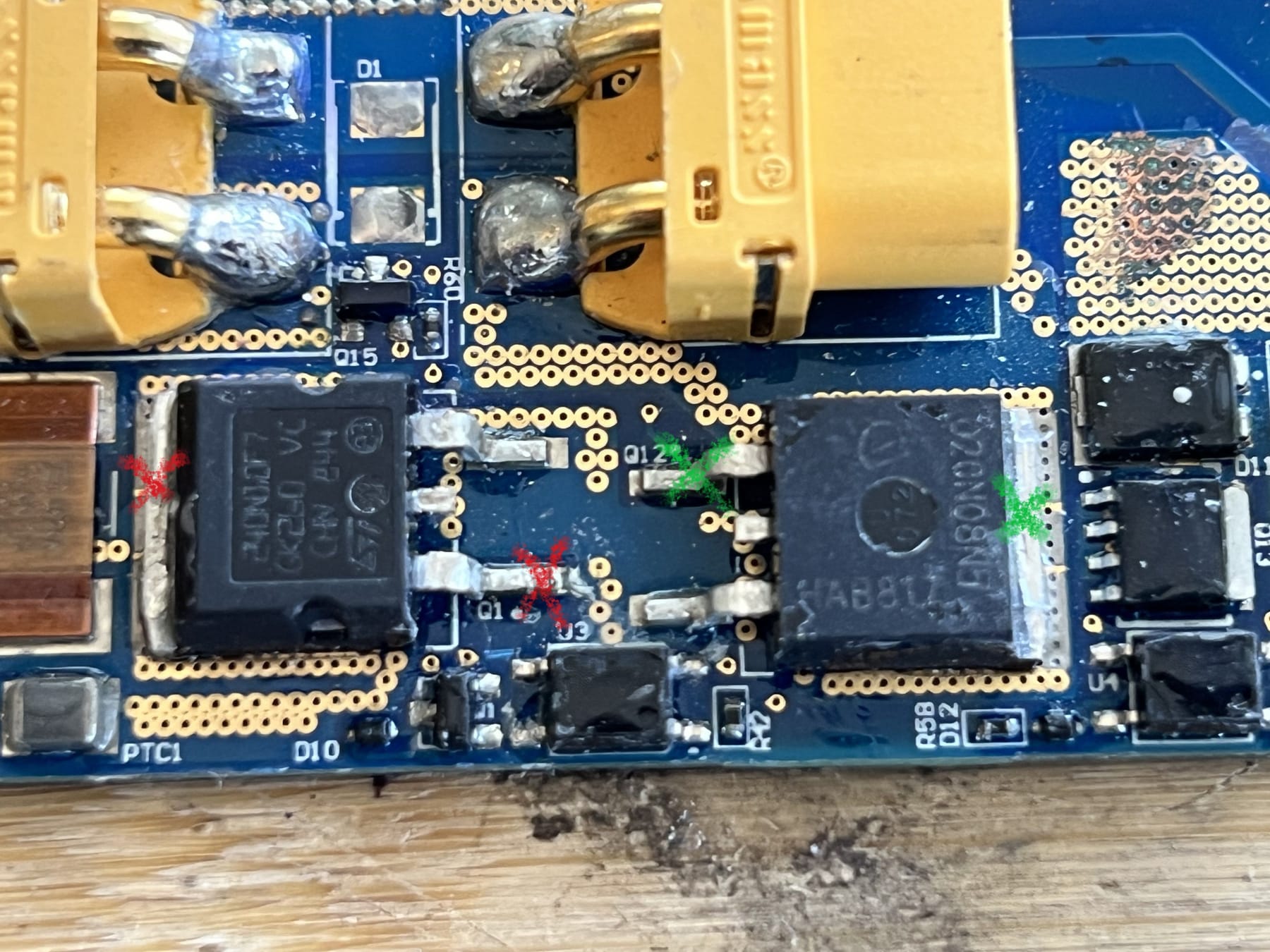
                    @aiden1983 Probe the areas red "x" to red "x" and green "x" to green x with a ohm meter set to 200k and there should be no continuity.IMG_0057.jpg

                    A 1 Reply Last reply Reply Quote 1
                    • A
                      aiden1983 @Lemur last edited by

                      @lemur thank you! The pint is slightly different but I was able to see than 4 out of the 6 MOSFET were blown. Took them off my board and no longer have a short. Just need my replacements now :)

                      L 1 Reply Last reply Reply Quote 1
                      • L
                        Lemur @aiden1983 last edited by

                        @aiden1983 Sorry, I got mixed up with another post asking about a Pint bms.
                        These are the mosfets you need. IMG_E0063[1].JPG

                        A 1 Reply Last reply Reply Quote 1
                        • A
                          aiden1983 @Lemur last edited by

                          @lemur thanks for the reply! I removed the mosfets and noticed that on Q2 the source and drain are still short. Do you have an idea what component could be causing the short still? It is only in this location and it doesn’t appear that I have any solder bridges.

                          L 1 Reply Last reply Reply Quote 0
                          • L
                            Lemur @aiden1983 last edited by

                            @aiden1983 Do you mean there's still a short between the source and drain with all the mosfets removed?

                            A 1 Reply Last reply Reply Quote 0
                            • A
                              aiden1983 @Lemur last edited by

                              @lemur yes I believe so. When I measure the resistance I get approx. 850 ohms from the source to the drain. When the new mosfets are installed the diode mode shows voltage in both directions (source to drain and drain to source). I’m just trying to figure out what else could be blown causing these readings.

                              L 1 Reply Last reply Reply Quote 0
                              • L
                                Lemur @aiden1983 last edited by

                                @aiden1983 At this point I cannot give you any good advice, just guessing.
                                Just be aware throwing parts at it may not be cost effective and may cause a massive short that can cause a fire, ask me how I know.
                                I always plug in the battery outside after a repair.
                                Maybe look for a working Pint controller circuit board instead. Sorry.

                                1 Reply Last reply Reply Quote 0
                                • First post
                                  Last post