I've done a bit more experimenting.
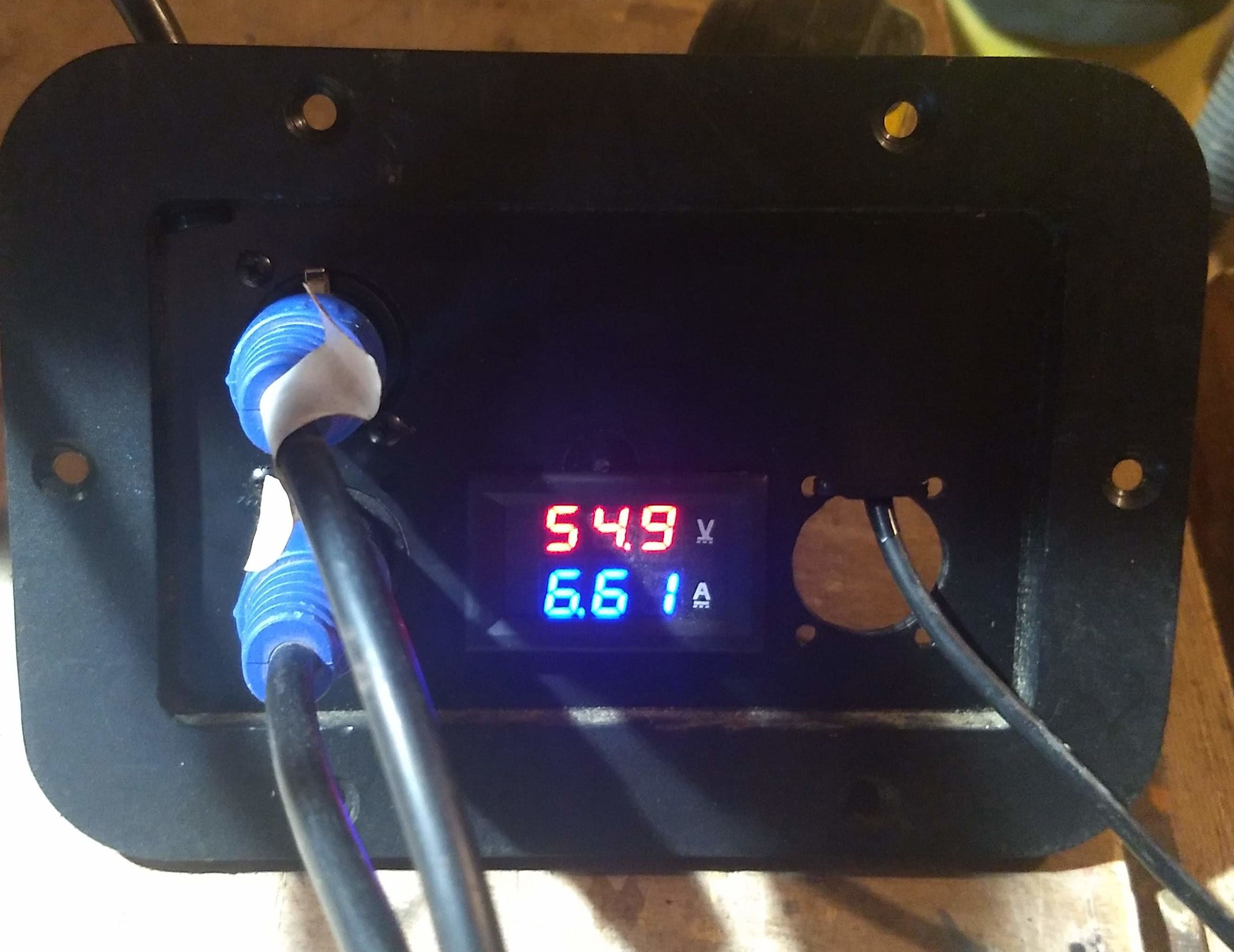
I made a splitter (dual male xlr to single female xlr) with a little lcd display giving the voltage and current passing through.
On a stock XR at about 80% battery, one stock XR charger gives about 3 A then this value slowly decreases as the charge goes on (we're already in the constant voltage phase). Plugging both XR stock chargers does not change anything the amps remain at around 3 A and the decrease occurs. So far so good.
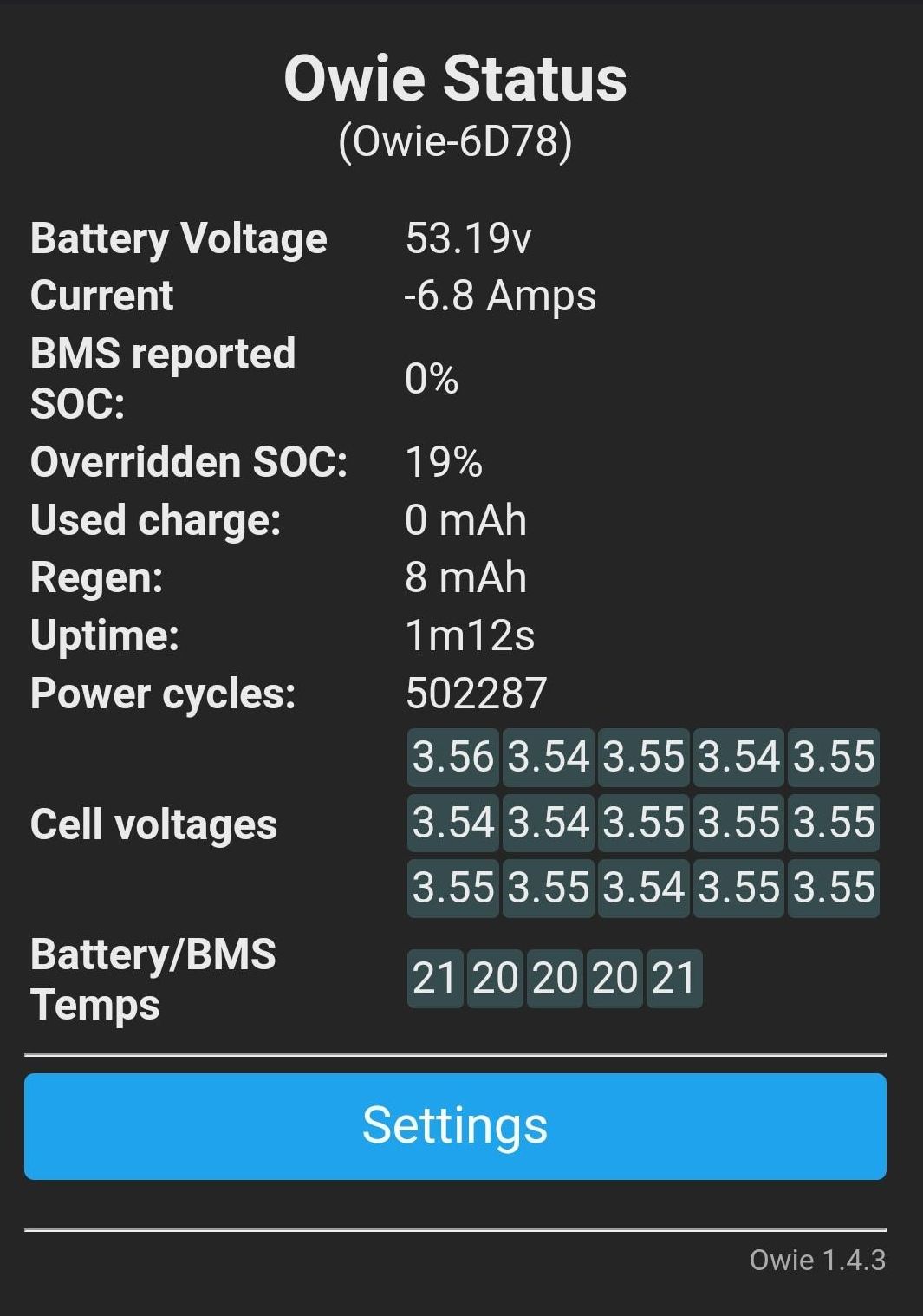
On a CBXR at about 20-40% battery (the battery gauge is a bit flaky and it depends if you base your reading on the app or the CBXR charts) one XR charger gives 3.3 A and both XR chargers together give 6.6 A.
This was both read on the display (6.6 A) and on the Owie app (6.8 A), so we can assume it's relatively accurate.
See pictures attached.


I only kept this plugged in for a few minutes at 6.6 A as I was worried that some components might not like having such a strong current for too long.
My CBXR is a 15s2p with cells M35A . These have a given maximum charging current of 1.7A.
https://www.molicel.com/wp-content/uploads/INR18650M35A-V2-80096.pdf
I am a bit out of my depth here but if I understand correctly, during the constant current charging phase if 6.6 A of charging current is applied, it is divided equally amongst each of the cells of each serie and therefore each cells only receive 0.44 A (6.6 / 15) right ?
Which does not seem that much and would be well within specs.
So the only thing that could suffer from the 6.6 A current would be the BMS. Anyone as any idea how the current flows through the BMS and if there are some "weak" components in it ?

